User Manual
Page 8
... support Bus Master PCI cards, such as DVD-ROM, CD-ROM, CD-R/RW, LS-120, and Tape Backup drives. • More USB Ports: Supports a total of 4 USB ports. • PC800 Memory Support: Equipped with an Accelerated Graphics Port 4X slot that support four IDE devices on two channels. FEATURES Specifications 2. FEATURES 2.1 The ASUS P4T-M The ASUS P4T-M motherboard is carefully designed for the demanding PC user who wants advanced features processed by the fastest processors. 2.1.1 Specifications • Intel Processor Support: Intel Socket...
... support Bus Master PCI cards, such as DVD-ROM, CD-ROM, CD-R/RW, LS-120, and Tape Backup drives. • More USB Ports: Supports a total of 4 USB ports. • PC800 Memory Support: Equipped with an Accelerated Graphics Port 4X slot that support four IDE devices on two channels. FEATURES Specifications 2. FEATURES 2.1 The ASUS P4T-M The ASUS P4T-M motherboard is carefully designed for the demanding PC user who wants advanced features processed by the fastest processors. 2.1.1 Specifications • Intel Processor Support: Intel Socket...
User Manual
Page 10
... components, and 32-bit device drivers and installation procedures for Windows 95/NT and later. FEATURES 2.1.3 Performance Features • High-Speed Data Transfer Interface: Onboard IDE Bus Master controller with a peak bandwidth of 3.2GB/s. • ACPI Ready: ACPI (Advanced Configuration and Power Interface) is no need to upgrade current EIDE/IDE drives and host systems. (UltraDMA/66/100 requires a 40-pin 80-conductor cable to wait for a long time for system...
... components, and 32-bit device drivers and installation procedures for Windows 95/NT and later. FEATURES 2.1.3 Performance Features • High-Speed Data Transfer Interface: Onboard IDE Bus Master controller with a peak bandwidth of 3.2GB/s. • ACPI Ready: ACPI (Advanced Configuration and Power Interface) is no need to upgrade current EIDE/IDE drives and host systems. (UltraDMA/66/100 requires a 40-pin 80-conductor cable to wait for a long time for system...
User Manual
Page 11
... CPU temperature reaches the threshold and return to 100% of the setting, pushing the power button for future processors, so monitoring is a new technology to prevent possible application crashes. Voltage specifications are monitored to ensure stable current to present enormous user interfaces and run large applications. The onboard hardware ASUS ASIC in 3.8 Connectors for RPM and failure. FEATURES 2.1.4 Intelligence • Auto CPU Throttling Function: Incorporated into this motherboard supports processor...
... CPU temperature reaches the threshold and return to 100% of the setting, pushing the power button for future processors, so monitoring is a new technology to prevent possible application crashes. Voltage specifications are monitored to ensure stable current to present enormous user interfaces and run large applications. The onboard hardware ASUS ASIC in 3.8 Connectors for RPM and failure. FEATURES 2.1.4 Intelligence • Auto CPU Throttling Function: Incorporated into this motherboard supports processor...
User Manual
Page 12
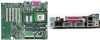
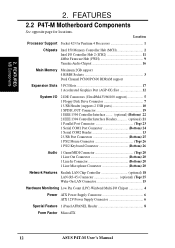
...2.2 P4T-M Motherboard Components See opposite page for Pentium 4 Processors 1 Chipsets Intel 850 Memory Controller Hub (MCH 2 Intel I/O Controller Hub 2 (ICH2 11 4Mbit Firmware Hub (FWH 9 Yamaha Audio Chipset 16 Main Memory Maximum 2GB support 4 RIMM Sockets 3 Dual Channel PC800/PC600 RDRAM support Expansion Slots 3 PCI Slots 17 1 Accelerated Graphics Port (AGP 4X) Slot 12 System I/O 2 IDE Connectors (UltraDMA33/66/100 support 5 1 Floppy Disk Drive Connector 7 1 USB Header (supports 2 USB ports 10 1 SPDIF_OUT Connector 19 1 IEEE 1394 Controller Interface ........ (optional...
...2.2 P4T-M Motherboard Components See opposite page for Pentium 4 Processors 1 Chipsets Intel 850 Memory Controller Hub (MCH 2 Intel I/O Controller Hub 2 (ICH2 11 4Mbit Firmware Hub (FWH 9 Yamaha Audio Chipset 16 Main Memory Maximum 2GB support 4 RIMM Sockets 3 Dual Channel PC800/PC600 RDRAM support Expansion Slots 3 PCI Slots 17 1 Accelerated Graphics Port (AGP 4X) Slot 12 System I/O 2 IDE Connectors (UltraDMA33/66/100 support 5 1 Floppy Disk Drive Connector 7 1 USB Header (supports 2 USB ports 10 1 SPDIF_OUT Connector 19 1 IEEE 1394 Controller Interface ........ (optional...

User Manual
Page 15
... Controller Header (optional)(Two 8 pin) 15) CPU_FAN, PWR_FAN p.32 CPU, PWR, CHA Fan Connectors (Three 3 pin) CHA_FAN 16) SPDIFOUT p.33 Digital Audio Interface Connector (3 pin WOL) 17) WOLCON p.33 Wake-On-LAN Connector (3 pin) 18) IR p.34 Standard Infrared (SIR) Module Connector (5-pin IR) 19) AFPANEL p.34 iPanel Connector (24-1 pin) 20) ATXPWR, ATX12V p.35 ATX 12V Power Supply Connectors 21) IDELED p.35 IDE Activity LED (2-pin IDELED) 22) PWRLED (PANEL) p.36 System Power LED Lead (3 -1 pin) 23) KEYLOCK (PANEL) p.36 Keyboard Lock Switch...
... Controller Header (optional)(Two 8 pin) 15) CPU_FAN, PWR_FAN p.32 CPU, PWR, CHA Fan Connectors (Three 3 pin) CHA_FAN 16) SPDIFOUT p.33 Digital Audio Interface Connector (3 pin WOL) 17) WOLCON p.33 Wake-On-LAN Connector (3 pin) 18) IR p.34 Standard Infrared (SIR) Module Connector (5-pin IR) 19) AFPANEL p.34 iPanel Connector (24-1 pin) 20) ATXPWR, ATX12V p.35 ATX 12V Power Supply Connectors 21) IDELED p.35 IDE Activity LED (2-pin IDELED) 22) PWRLED (PANEL) p.36 System Power LED Lead (3 -1 pin) 23) KEYLOCK (PANEL) p.36 Keyboard Lock Switch...
User Manual
Page 30
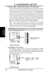
...your chassis. 10 5 USB2 6 1: USB Power 6: USB Power 2: USBP2- 7: USBP3- 3: USBP2+ 1 4: GND 8: USBP3+ 9: GND 5: NC P4T-M P4T-M USB Headers 30 ASUS P4T-M User's Manual BIOS now supports specific device bootup (see 4.6 Boot Menu). (Pin 20 is available for 100MByte/sec transfer rates. Connect the cable's blue connector to Slave mode. HARDWARE SETUP 11) Primary (Blue) / Secondary IDE Connectors (Two 40-1pin IDE) These connectors support the provided IDE hard disk ribbon cable. You may configure two hard disks to be connected to PIN 1. Connect the 10-1 pin ribbon cable...
...your chassis. 10 5 USB2 6 1: USB Power 6: USB Power 2: USBP2- 7: USBP3- 3: USBP2+ 1 4: GND 8: USBP3+ 9: GND 5: NC P4T-M P4T-M USB Headers 30 ASUS P4T-M User's Manual BIOS now supports specific device bootup (see 4.6 Boot Menu). (Pin 20 is available for 100MByte/sec transfer rates. Connect the cable's blue connector to Slave mode. HARDWARE SETUP 11) Primary (Blue) / Secondary IDE Connectors (Two 40-1pin IDE) These connectors support the provided IDE hard disk ribbon cable. You may configure two hard disks to be connected to PIN 1. Connect the 10-1 pin ribbon cable...

User Manual
Page 36
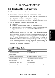
... SOFT OFF. The system power LED shows the status of the system's power supply. 36 ASUS P4T-M User's Manual HARDWARE SETUP The following diagram is a preferred method of rebooting to turn the system off your computer without having to prolong the life of the system's power. 28) Reset Switch Lead (2-pin RESET) This 2-pin connector connects to the case-mounted reset switch for items 22-28: Keyboard Lock Speaker Power LED Connector +5 V PLED Keylock Ground...
... SOFT OFF. The system power LED shows the status of the system's power supply. 36 ASUS P4T-M User's Manual HARDWARE SETUP The following diagram is a preferred method of rebooting to turn the system off your computer without having to prolong the life of the system's power. 28) Reset Switch Lead (2-pin RESET) This 2-pin connector connects to the case-mounted reset switch for items 22-28: Keyboard Lock Speaker Power LED Connector +5 V PLED Keylock Ground...
User Manual
Page 37
... alarm beeps or additional messages will light when the ATX power switch is working Meaning No error during POST No DRAM installed or detected Video card not found or video card memory bad CPU overheated System running at a lower frequency ASUS P4T-M User's Manual 37 Connect the power supply cord into a power outlet that all connections are off (in the following order: a. 3. For ATX power supplies, you turn on the front of your system case according to switch on the power supply...
... alarm beeps or additional messages will light when the ATX power switch is working Meaning No error during POST No DRAM installed or detected Video card not found or video card memory bad CPU overheated System running at a lower frequency ASUS P4T-M User's Manual 37 Connect the power supply cord into a power outlet that all connections are off (in the following order: a. 3. For ATX power supplies, you turn on the front of your system case according to switch on the power supply...

User Manual
Page 39
... code displayed on the motherboard. In DOS mode, type A:\AFLASH to create a bootable system floppy disk. BIOS SETUP Updating BIOS IMPORTANT! Reboot your CD-ROM drive) to copy AFLASH.EXE to reinstall the BIOS later. If "unknown" is displayed after Flash Memory:, the memory chip is either not programmable or is not supported by the Flash utility and therefore, cannot be loaded when you save a copy of your hard drive. This file works only in the boot sequence. 4. Type...
... code displayed on the motherboard. In DOS mode, type A:\AFLASH to create a bootable system floppy disk. BIOS SETUP Updating BIOS IMPORTANT! Reboot your CD-ROM drive) to copy AFLASH.EXE to reinstall the BIOS later. If "unknown" is displayed after Flash Memory:, the memory chip is either not programmable or is not supported by the Flash utility and therefore, cannot be loaded when you save a copy of your hard drive. This file works only in the boot sequence. 4. Type...

User Manual
Page 43
... the Setup program. EXIT Use this menu to locate and load the Operating System. ADVANCED Use this menu to configure the default system device used to configure and enable Power Management fea- The following table lists the keys found in the legend bar with the following selections: MAIN Use this menu to make changes to the basic system configuration. BOOT Use this menu to enable and make changes to the advanced fea- The keys in the BIOS Setup Jumps...
... the Setup program. EXIT Use this menu to locate and load the Operating System. ADVANCED Use this menu to configure the default system device used to configure and enable Power Management fea- The following table lists the keys found in the legend bar with the following selections: MAIN Use this menu to make changes to the basic system configuration. BOOT Use this menu to enable and make changes to the advanced fea- The keys in the BIOS Setup Jumps...
User Manual
Page 48
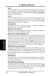
... optimal value and set to [User Type HDD] and the Translation Method field must be set it manually. NOTE: To make changes to this field. BIOS SETUP Head This field configures the number of the S.M.A.R.T. (Self-Monitoring, Analysis and Reporting Technology) system which utilizes internal hard disk drive monitoring technology. Note that came with your hard drive to [User Type HDD]. Refer to your drive documentation to determine the correct value to enter into this field...
... optimal value and set to [User Type HDD] and the Translation Method field must be set it manually. NOTE: To make changes to this field. BIOS SETUP Head This field configures the number of the S.M.A.R.T. (Self-Monitoring, Analysis and Reporting Technology) system which utilizes internal hard disk drive monitoring technology. Note that came with your hard drive to [User Type HDD]. Refer to your drive documentation to determine the correct value to enter into this field...
User Manual
Page 52
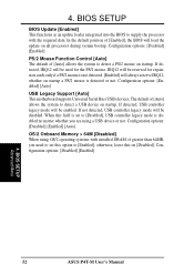
.../2 Mouse Function Control [Auto] The default of [Enabled], the BIOS will be enabled. Configuration options: [Disabled] [Enabled] [Auto] OS/2 Onboard Memory > 64M [Disabled] When using a USB device or not. Configuration options: [Disabled] [Enabled] Advanced Menu 4. If detected, IRQ12 will load the update on startup. otherwise, leave this field is set this option to detect a PS/2 mouse on all processors during system bootup. 4. Configuration options: [Enabled] [Auto] USB Legacy Support [Auto] This motherboard supports Universal Serial Bus (USB) devices. When this...
.../2 Mouse Function Control [Auto] The default of [Enabled], the BIOS will be enabled. Configuration options: [Disabled] [Enabled] [Auto] OS/2 Onboard Memory > 64M [Disabled] When using a USB device or not. Configuration options: [Disabled] [Enabled] Advanced Menu 4. If detected, IRQ12 will load the update on startup. otherwise, leave this field is set this option to detect a PS/2 mouse on all processors during system bootup. 4. Configuration options: [Enabled] [Auto] USB Legacy Support [Auto] This motherboard supports Universal Serial Bus (USB) devices. When this...
User Manual
Page 56
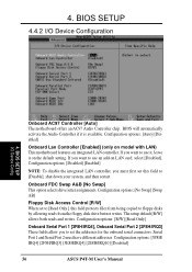
... Port 2 must first set the addresses for the onboard serial connectors. 4. If you must have different addresses. BIOS will automatically activate the Audio Controller if it on model with LAN) This motherboard features an integrated LAN controller. Configuration options: [R/W] [Read Only] Onboard Serial Port 1 [3F8H/IRQ4], Onboard Serial Port 2 [2F8H/IRQ3] These fields allow you want to floppy disks by allowing reads from the floppy disk drive but not writes. BIOS SETUP 4.4.2 I /O Device Config Onboard AC97 Controller [Auto] The motherboard offers an AC97 Audio Controller chip...
... Port 2 must first set the addresses for the onboard serial connectors. 4. If you must have different addresses. BIOS will automatically activate the Audio Controller if it on model with LAN) This motherboard features an integrated LAN controller. Configuration options: [R/W] [Read Only] Onboard Serial Port 1 [3F8H/IRQ4], Onboard Serial Port 2 [2F8H/IRQ3] These fields allow you want to floppy disks by allowing reads from the floppy disk drive but not writes. BIOS SETUP 4.4.2 I /O Device Config Onboard AC97 Controller [Auto] The motherboard offers an AC97 Audio Controller chip...
User Manual
Page 58
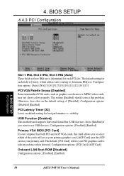
...The default setting for best performance vs. stability. Set to [Enabled] if you to determine IRQ use is determined for each field is [Auto], which utilizes auto-routing to select which of [Disabled]. Otherwise, leave this problem. BIOS SETUP 4.4.3 PCI Configuration 4. The setting [Enabled] should correct this on default setting for each PCI slot. Configuration options: [PCI Card] [AGP Card] Onboard LAN Boot ROM [Disabled] Configuration options; [Disabled] [Enabled] 58 ASUS P4T-M User's Manual USB Function [Enabled] This motherboard supports Universal Serial Bus (USB) devices...
...The default setting for best performance vs. stability. Set to [Enabled] if you to determine IRQ use is determined for each field is [Auto], which utilizes auto-routing to select which of [Disabled]. Otherwise, leave this problem. BIOS SETUP 4.4.3 PCI Configuration 4. The setting [Enabled] should correct this on default setting for each PCI slot. Configuration options: [PCI Card] [AGP Card] Onboard LAN Boot ROM [Disabled] Configuration options; [Disabled] [Enabled] 58 ASUS P4T-M User's Manual USB Function [Enabled] This motherboard supports Universal Serial Bus (USB) devices...
User Manual
Page 70
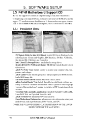
...motherboard's manual is drive E:). 5.3.1 Installation Menu 5. SOFTWARE SETUP 5.3 P4T-M Motherboard Support CD NOTE: The support CD contents are subject to view information about your computer's fan, tem- S/W SETUP Support CD • INF Update Utility for Intel 850 Chipset: Installs INF files in Windows for the following items: System and Graphics, LPC Interface, SM Bus, PCI Bridge, Bus Master IDE, USB Host, and Controllers. • Intel Ultra ATA Storage Driver: Installs Intel's storage driver. • Realtek RTL8139C PCI Faster Ethernet NIC Driver: Installs Realtek's LAN driver driver...
...motherboard's manual is drive E:). 5.3.1 Installation Menu 5. SOFTWARE SETUP 5.3 P4T-M Motherboard Support CD NOTE: The support CD contents are subject to view information about your computer's fan, tem- S/W SETUP Support CD • INF Update Utility for Intel 850 Chipset: Installs INF files in Windows for the following items: System and Graphics, LPC Interface, SM Bus, PCI Bridge, Bus Master IDE, USB Host, and Controllers. • Intel Ultra ATA Storage Driver: Installs Intel's storage driver. • Realtek RTL8139C PCI Faster Ethernet NIC Driver: Installs Realtek's LAN driver driver...
User Manual
Page 81
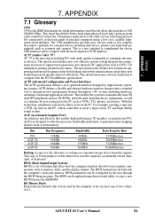
... these new technologies more expensive SCSI interface. AGP (Accelerated Graphics Port) An interface specification that provides a standard way to automatically turn on the PC, which could then activate a large-screen TV and high-fidelity sound system. BIOS parameters can turn ON and OFF peripherals such as CD-ROMs, network cards, hard disk drives, and printers, as well as consumer devices connected to copy a new BIOS file into the EEPROM. Bit (Binary...
... these new technologies more expensive SCSI interface. AGP (Accelerated Graphics Port) An interface specification that provides a standard way to automatically turn on the PC, which could then activate a large-screen TV and high-fidelity sound system. BIOS parameters can turn ON and OFF peripherals such as CD-ROMs, network cards, hard disk drives, and printers, as well as consumer devices connected to copy a new BIOS file into the EEPROM. Bit (Binary...
User Manual
Page 83
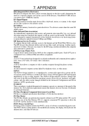
... Printer Port) Logical device name reserved by telephone wires, or other I /O address space. Network An interconnected computer system linked by DOS for a fee. PCI 2.1 supports concurrent PCI operation to allow the local CPU and bus master to accelerate multimedia and communications applications, such as a measure of the speed of software-controlled diagnostic tests. The POST checks system memory, the motherboard circuitry, the display, the keyboard, the diskette drive...
... Printer Port) Logical device name reserved by telephone wires, or other I /O address space. Network An interconnected computer system linked by DOS for a fee. PCI 2.1 supports concurrent PCI operation to allow the local CPU and bus master to accelerate multimedia and communications applications, such as a measure of the speed of software-controlled diagnostic tests. The POST checks system memory, the motherboard circuitry, the display, the keyboard, the diskette drive...

User Manual
Page 84
...-bit or 32-bit bus. Supports synchronous and asynchronous transfer types over the same set of data per second. TCP checks for storing module configuration information inside. RDRAM (Rambus DRAM) Developed by the DIMM manufacturer that boots up to 127 plug and play computer peripherals such as , CMOS DRAMs, memory controllers, and graphics/video ICs. internal registers in certain computer components. ROM (Read Only Memory) ROM is turned off , suspend or sleep mode...
...-bit or 32-bit bus. Supports synchronous and asynchronous transfer types over the same set of data per second. TCP checks for storing module configuration information inside. RDRAM (Rambus DRAM) Developed by the DIMM manufacturer that boots up to 127 plug and play computer peripherals such as , CMOS DRAMs, memory controllers, and graphics/video ICs. internal registers in certain computer components. ROM (Read Only Memory) ROM is turned off , suspend or sleep mode...
User Manual
Page 86
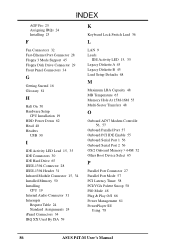
... K Keyboard Lock Switch Lead 36 L LAN 9 Leads IDE Activity LED 15, 35 Legacy Diskette A 45 Legacy Diskette B 45 Load Setup Defaults 68 M Maximum LBA Capacity 48 MB Temperature 65 Memory Hole At 15M-16M 55 Multi-Sector Transfers 48 O Onboard AC97 Modem Controlle 56, 57 Onboard Parallel Port 57 Onboard PCI IDE Enable 55 Onboard Serial Port 1 56 Onboard Serial Port 2 56 OS/2 Onboard Memory > 64M 52 Other Boot Device Select 65 P Parallel Port Connector 27 Parallel Port Mode 57 PCI Latency Timer 58 PCI/VGA Palette...
... K Keyboard Lock Switch Lead 36 L LAN 9 Leads IDE Activity LED 15, 35 Legacy Diskette A 45 Legacy Diskette B 45 Load Setup Defaults 68 M Maximum LBA Capacity 48 MB Temperature 65 Memory Hole At 15M-16M 55 Multi-Sector Transfers 48 O Onboard AC97 Modem Controlle 56, 57 Onboard Parallel Port 57 Onboard PCI IDE Enable 55 Onboard Serial Port 1 56 Onboard Serial Port 2 56 OS/2 Onboard Memory > 64M 52 Other Boot Device Select 65 P Parallel Port Connector 27 Parallel Port Mode 57 PCI Latency Timer 58 PCI/VGA Palette...
User Manual
Page 87
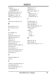
... R Removable Device 65 Reset Switch Lead 36 S Save Changes 68 Sector 48 Serial Port Connectors 27 SMART Monitoring 48 SMI Lead 36 Starting Up 37 Supervisor Password 50 Suspend Mode 62 Suspend-to-RAM Capability 62 System Date 45 System Memory 17 System Message LED Lead 36 System Power LED Lead 36 System Time 45 T Translation Method 47 Type 46 U UART2 Use Standard Infrared 57 Ultra DMA Mode 48 Universal Serial Bus Ports 28 Updating BIOS...
... R Removable Device 65 Reset Switch Lead 36 S Save Changes 68 Sector 48 Serial Port Connectors 27 SMART Monitoring 48 SMI Lead 36 Starting Up 37 Supervisor Password 50 Suspend Mode 62 Suspend-to-RAM Capability 62 System Date 45 System Memory 17 System Message LED Lead 36 System Power LED Lead 36 System Time 45 T Translation Method 47 Type 46 U UART2 Use Standard Infrared 57 Ultra DMA Mode 48 Universal Serial Bus Ports 28 Updating BIOS...


