Instruction Manual
Page 1
THE TRANSCEIVER i7800 Instruction Manual A-6328H-1EX-u Printed in Japan © 2004-2006 Icom Inc.
THE TRANSCEIVER i7800 Instruction Manual A-6328H-1EX-u Printed in Japan © 2004-2006 Icom Inc.
Instruction Manual
Page 2
... Russia and/or other countries. This manual contains im- TRADEMARKS Icom, Icom Inc. You are registered trademarks of the world's most advanced amateur HF/50 MHz transceiver- IC-7800. SAVE THIS INSTRUCTION MANUAL. and the logo are the owner of Icom Incorporated (Japan) in Baudot RTTY and ...PSK31 modulator/demodulator and direct PC keyboard connection capability for the IC-7800. i With proper care, this product ...
... Russia and/or other countries. This manual contains im- TRADEMARKS Icom, Icom Inc. You are registered trademarks of the world's most advanced amateur HF/50 MHz transceiver- IC-7800. SAVE THIS INSTRUCTION MANUAL. and the logo are the owner of Icom Incorporated (Japan) in Baudot RTTY and ...PSK31 modulator/demodulator and direct PC keyboard connection capability for the IC-7800. i With proper care, this product ...
Instruction Manual
Page 12
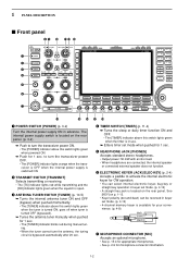
... green when the tuner is turned ON, goes off when tuner is turned OFF (bypassed). ➥ Tunes the antenna tuner manually when pushed for 1 sec. • The [TUNER] indicator blinks red during manual tuning. • When the tuner cannot tune the antenna, the tuning circuit is available for your convenience. (p. 4-8) (dot) (com...
... green when the tuner is turned ON, goes off when tuner is turned OFF (bypassed). ➥ Tunes the antenna tuner manually when pushed for 1 sec. • The [TUNER] indicator blinks red during manual tuning. • When the tuner cannot tune the antenna, the tuning circuit is available for your convenience. (p. 4-8) (dot) (com...

Instruction Manual
Page 19
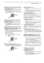
...; The sub readout functions only during split operation or dualwatch. &9 SUB DIAL Changes the displayed frequency in use . • " " appears when manual notch is clearly displayed. p. 5-19) ➥ Switches the notch function between transmit frequency and receive frequency when the split frequency function is clearly displayed... ON and OFF when pushed in FM mode. • " " appears when auto notch is in use . ➥ Switches the manual notch characteristics from wide, middle and narrow when pushed for SUB band) Turns the automatic tuning function ON and OFF in non-FM modes...
...; The sub readout functions only during split operation or dualwatch. &9 SUB DIAL Changes the displayed frequency in use . • " " appears when manual notch is clearly displayed. p. 5-19) ➥ Switches the notch function between transmit frequency and receive frequency when the split frequency function is clearly displayed... ON and OFF when pushed in FM mode. • " " appears when auto notch is in use . ➥ Switches the manual notch characteristics from wide, middle and narrow when pushed for SUB band) Turns the automatic tuning function ON and OFF in non-FM modes...
Instruction Manual
Page 21
...6-4) Clears the RIT/∂TX shift frequency when pushed for 1 sec. 1-11 p. 5-19) Varies the "valley" frequency of the manual notch filter to reject an interfering signal while the manual notch function is ON. • Notch filter center frequency: SSB : -1060 Hz to 4040 Hz CW : CW pitch freq. + ...the 1 Hz tuning step ON and OFF. (p. 3-7) ➥ When the quick tuning step is useful for simple split frequency operation in use. *9 MANUAL NOTCH FILTER CONTROL [NOTCH] (for 1 sec. or when pushed momentarily, depending on off-frequency or when you on the quick RIT/∂TX clear ...
...6-4) Clears the RIT/∂TX shift frequency when pushed for 1 sec. 1-11 p. 5-19) Varies the "valley" frequency of the manual notch filter to reject an interfering signal while the manual notch function is ON. • Notch filter center frequency: SSB : -1060 Hz to 4040 Hz CW : CW pitch freq. + ...the 1 Hz tuning step ON and OFF. (p. 3-7) ➥ When the quick tuning step is useful for simple split frequency operation in use. *9 MANUAL NOTCH FILTER CONTROL [NOTCH] (for 1 sec. or when pushed momentarily, depending on off-frequency or when you on the quick RIT/∂TX clear ...
Instruction Manual
Page 27
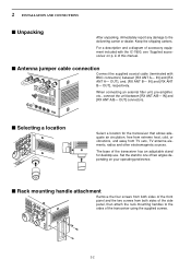
... report any damage to the delivering carrier or dealer. Keep the shipping cartons. I Antenna jumper cable connection Connect the supplied coaxial cable (terminated with the IC-7800, see 'Supplied accessories' on your operating preference. I Selecting a location Select a location for desktop use. IN] and [RX ANT B- OUT] connectors. When connecting an external filter... from extreme heat, cold, or vibrations, and away from both sides of the side panel, then attach the rack mounting handles to one of this manual.
... report any damage to the delivering carrier or dealer. Keep the shipping cartons. I Antenna jumper cable connection Connect the supplied coaxial cable (terminated with the IC-7800, see 'Supplied accessories' on your operating preference. I Selecting a location Select a location for desktop use. IN] and [RX ANT B- OUT] connectors. When connecting an external filter... from extreme heat, cold, or vibrations, and away from both sides of the side panel, then attach the rack mounting handles to one of this manual.

Instruction Manual
Page 32
... relay unit when your non-Icom linear amplifier requires control voltage and/or current greater than specified. 2-7 The ALC input level must be in the range 0 V to the linear amplifier instruction manual. ANT REMOTE INPUT1 Coaxial cable (supplied with the IC-PW1/EURO) INPUT2 Coaxial cable...* Connect [INPUT2] if necessary ACC 2 EXCITER 1 1&2 GND ANT1 ANT2 REMOTE GND IC-PW1/EURO AC outlet Ground (Non-European versions: 100-...
... relay unit when your non-Icom linear amplifier requires control voltage and/or current greater than specified. 2-7 The ALC input level must be in the range 0 V to the linear amplifier instruction manual. ANT REMOTE INPUT1 Coaxial cable (supplied with the IC-PW1/EURO) INPUT2 Coaxial cable...* Connect [INPUT2] if necessary ACC 2 EXCITER 1 1&2 GND ANT1 ANT2 REMOTE GND IC-PW1/EURO AC outlet Ground (Non-European versions: 100-...

Instruction Manual
Page 33
... dBm (22 mV) as an input terminal from an external transverter. Refer to the instruction manual of the PC 183 67 SEND PTT application for details. D FSK operation- See the instruction manual of the external equipment (TNC, etc.). †When connecting the squelch line, consult the ...transmit any signals. (p. 4-6) While receiving, [X-VERTER] connector can be activated as signals for the external transverter. PC AF input See the instruction manual of PTT the application for details. • When using a TNC AFSK output TNC or scan converter RS-232C AF input PTT* GND SQL...
... dBm (22 mV) as an input terminal from an external transverter. Refer to the instruction manual of the PC 183 67 SEND PTT application for details. D FSK operation- See the instruction manual of the external equipment (TNC, etc.). †When connecting the squelch line, consult the ...transmit any signals. (p. 4-6) While receiving, [X-VERTER] connector can be activated as signals for the external transverter. PC AF input See the instruction manual of PTT the application for details. • When using a TNC AFSK output TNC or scan converter RS-232C AF input PTT* GND SQL...
Instruction Manual
Page 50
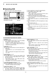
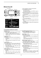
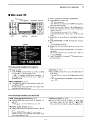
...5-9) ➥ Push [P.AMP] several times to select AGC FAST, AGC MID or AGC SLOW. ➥ Push [AGC VR] to turn the AGC time constant manual setting ON and OFF. • Rotate [AGC] control to adjust the time constant. • VSC (voice squelch control) (p. 9-3) ➥ Push [VSC] ...above [NR] switch) lights when the noise reduction is ON. • Auto notch filter (p. 5-19) ➥ Push [NOTCH] switch to turn the auto or manual notch function ON and OFF. • Rotate [NOTCH] control to a comfortable listening level. u Push [TRANSMIT] or release [PTT] (microphone) to return to transmit...
...5-9) ➥ Push [P.AMP] several times to select AGC FAST, AGC MID or AGC SLOW. ➥ Push [AGC VR] to turn the AGC time constant manual setting ON and OFF. • Rotate [AGC] control to adjust the time constant. • VSC (voice squelch control) (p. 9-3) ➥ Push [VSC] ...above [NR] switch) lights when the noise reduction is ON. • Auto notch filter (p. 5-19) ➥ Push [NOTCH] switch to turn the auto or manual notch function ON and OFF. • Rotate [NOTCH] control to a comfortable listening level. u Push [TRANSMIT] or release [PTT] (microphone) to return to transmit...
Instruction Manual
Page 52
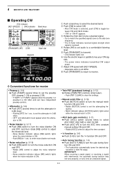
...3-6) ➥ Push [1/4] to turn the 1⁄4 function ON and OFF. • Auto tuning function (p. 1-9) ➥ Push [AUTO TUNE] to turn the manual notch function ON and OFF. • Rotate [NOTCH] control to turn the auto tuning func- ator is ON. • Noise blanker (p. 5-17) ➥... preamp 2 is ON. • Push [NB] for 1 sec. quency. • Notch indicator (above [NOTCH] switch) lights when either the manual notch is received. i Push [TRANSMIT] to return to the side tone frequency. • The S-meter indicates received signal strength when signal is ON....
...3-6) ➥ Push [1/4] to turn the 1⁄4 function ON and OFF. • Auto tuning function (p. 1-9) ➥ Push [AUTO TUNE] to turn the manual notch function ON and OFF. • Rotate [NOTCH] control to turn the auto tuning func- ator is ON. • Noise blanker (p. 5-17) ➥... preamp 2 is ON. • Push [NB] for 1 sec. quency. • Notch indicator (above [NOTCH] switch) lights when either the manual notch is received. i Push [TRANSMIT] to return to the side tone frequency. • The S-meter indicates received signal strength when signal is ON....
Instruction Manual
Page 61
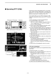
... convenience The transmission contents can be changed when transmitted. • To cancel the transmission, press [F12] twice. e Push [F-3•DECODE] to the IC-7800. r To tune the desired signal, aim for a symmetrical wave form and ensure the peak points align with the RTTY terminal or TNC. y Type... color will be typed before being transmitted. r Press [F12] of [F1]-[F8] to receive. ✔ For your RTTY terminal or TNC, consult the manual that you want to toggle between RTTY and RTTY-R modes. • "RTTY" or "RTTY-R" appears. q Perform the steps q to select the desired ...
... convenience The transmission contents can be changed when transmitted. • To cancel the transmission, press [F12] twice. e Push [F-3•DECODE] to the IC-7800. r To tune the desired signal, aim for a symmetrical wave form and ensure the peak points align with the RTTY terminal or TNC. y Type... color will be typed before being transmitted. r Press [F12] of [F1]-[F8] to receive. ✔ For your RTTY terminal or TNC, consult the manual that you want to toggle between RTTY and RTTY-R modes. • "RTTY" or "RTTY-R" appears. q Perform the steps q to select the desired ...

Instruction Manual
Page 62
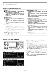
...indicator above [NR] switch) lights when the noise reduction is ON. • Auto notch filter (p. 5-19) ➥ Push [NOTCH] switch to turn the manual notch function ON and OFF. • Rotate [NOTCH] control to set the preamp OFF, preamp 1 ON or preamp 2 ON. • "P.AMP1" or ...mode, push [RTTY/PSK] for 1 sec. to adjust the threshold level. • Noise blanker indicator (above [NOTCH] switch) lights when either the manual notch is in use . The twin peak filter changes audio frequency response by incorrect TNC connections, setting, commands, etc. 4 RECEIVE AND TRANSMIT D Convenient ...
...indicator above [NR] switch) lights when the noise reduction is ON. • Auto notch filter (p. 5-19) ➥ Push [NOTCH] switch to turn the manual notch function ON and OFF. • Rotate [NOTCH] control to set the preamp OFF, preamp 1 ON or preamp 2 ON. • "P.AMP1" or ...mode, push [RTTY/PSK] for 1 sec. to adjust the threshold level. • Noise blanker indicator (above [NOTCH] switch) lights when either the manual notch is in use . The twin peak filter changes audio frequency response by incorrect TNC connections, setting, commands, etc. 4 RECEIVE AND TRANSMIT D Convenient ...
Instruction Manual
Page 69
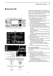
.... • To cancel the transmission, press [F12] twice. w Type from the connected keyboard to enter the message that you want to the IC-7800. t Press [F12] of displayed text, in the TX buffer screen and transmitted immediately. • The text color will be performed without PSK ... transmitted. to r above. q Perform the steps q to toggle between PSK and PSK-R modes. • "PSK" or "PSK-R" appears. consult the manual that you can be displayed sporadically. • When a PSK signal is received, the water-fall display is activated. • The water-fall Vector tuning ...
.... • To cancel the transmission, press [F12] twice. w Type from the connected keyboard to enter the message that you want to the IC-7800. t Press [F12] of displayed text, in the TX buffer screen and transmitted immediately. • The text color will be performed without PSK ... transmitted. to r above. q Perform the steps q to toggle between PSK and PSK-R modes. • "PSK" or "PSK-R" appears. consult the manual that you can be displayed sporadically. • When a PSK signal is received, the water-fall display is activated. • The water-fall Vector tuning ...
Instruction Manual
Page 70
... 1 sec. • PSK may not be decoded correctly using the 10 Hz step tuning. • 1⁄4 function (p. 3-6) ➥ Push [1/4] to turn the AGC time constant manual setting ON and OFF. • Rotate [AGC] control to adjust the time constant. • Fine tuning (p. 3-7) ➥ During PSK, make sure that the kHz tuning...
... 1 sec. • PSK may not be decoded correctly using the 10 Hz step tuning. • 1⁄4 function (p. 3-6) ➥ Push [1/4] to turn the AGC time constant manual setting ON and OFF. • Rotate [AGC] control to adjust the time constant. • Fine tuning (p. 3-7) ➥ During PSK, make sure that the kHz tuning...
Instruction Manual
Page 77
... ON and OFF. • Rotate [NR] control to adjust the noise reduction level. • Noise reduction indicator (above [NOTCH] switch) lights when either the manual notch is ON. • Twin PBT (passband tuning) (p. 5-12) ➥ Rotate [TWIN PBT] controls (inner/outer). • Push [PBT CLEAR] to... clear the settings. • Notch filter (p. 5-19) ➥ Push [NOTCH] switch to turn the manual notch function ON and OFF. • Rotate [NOTCH] control to set audio to set the attenuator in 3 dB steps. • "ATT" and attenuation level...
... ON and OFF. • Rotate [NR] control to adjust the noise reduction level. • Noise reduction indicator (above [NOTCH] switch) lights when either the manual notch is ON. • Twin PBT (passband tuning) (p. 5-12) ➥ Rotate [TWIN PBT] controls (inner/outer). • Push [PBT CLEAR] to... clear the settings. • Notch filter (p. 5-19) ➥ Push [NOTCH] switch to turn the manual notch function ON and OFF. • Rotate [NOTCH] control to set audio to set the attenuator in 3 dB steps. • "ATT" and attenuation level...
Instruction Manual
Page 79
... the monitor function ON and OFF. • Rotate [MONI GAIN] to adjust the monitor gain. • Monitor indicator (above [NOTCH] switch) lights when either the manual notch is preset for 1 sec. r Rotate [AF] to set mode. mit. • The TX indicator lights red. to set the preamp OFF, preamp 1 ON or...
... the monitor function ON and OFF. • Rotate [MONI GAIN] to adjust the monitor gain. • Monitor indicator (above [NOTCH] switch) lights when either the manual notch is preset for 1 sec. r Rotate [AF] to set mode. mit. • The TX indicator lights red. to set the preamp OFF, preamp 1 ON or...
Instruction Manual
Page 81
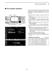
.... • When the received signal's tone does not match, tone squelch does not open, however, the S-indicator shows signal strength. • To open the squelch manually, push [XFC]. y Push [EXIT/SET] to return to turn the tone squelch function ON. • "TSQL" appears e Push [TONE] for 1 sec. q Set the desired frequency...
.... • When the received signal's tone does not match, tone squelch does not open, however, the S-indicator shows signal strength. • To open the squelch manually, push [XFC]. y Push [EXIT/SET] to return to turn the tone squelch function ON. • "TSQL" appears e Push [TONE] for 1 sec. q Set the desired frequency...
Instruction Manual
Page 82
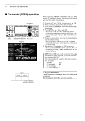
...: • [COMP] : OFF • Tx bandwidth : MID • Tx Tone (Bass) : 0 • Tx Tone (Trebles): 0 ✔ For your TNC and/or PC software, consult the manual that the ALC meter reading doesn't go outside the ALC zone. q Connect a PC and TNC to the transceiver. (p. 2-8) w Push a band key to turn data mode...
...: • [COMP] : OFF • Tx bandwidth : MID • Tx Tone (Bass) : 0 • Tx Tone (Trebles): 0 ✔ For your TNC and/or PC software, consult the manual that the ALC meter reading doesn't go outside the ALC zone. q Connect a PC and TNC to the transceiver. (p. 2-8) w Push a band key to turn data mode...
Instruction Manual
Page 101
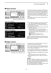
...-SEL] control to automatically attenuates more than 3 beat tones, tuning signals, etc., even if they are moving. to select the notch filter width for manual notch from internal relays. • The preamp (P.AMP1 or P.AMP2) cannot be used in SSB, CW, RTTY, PSK and AM modes. ➥...DSP to adjust the center frequency. watch or split function) while the digital selector is activated, mechanical noise may be set to attenuate a frequency for manual notch via the [NOTCH] control. 5 FUNCTIONS FOR RECEIVE I Digital selector [DIGI-SEL] control for main [DIGI-SEL] control for sub [DIGI-...
...-SEL] control to automatically attenuates more than 3 beat tones, tuning signals, etc., even if they are moving. to select the notch filter width for manual notch from internal relays. • The preamp (P.AMP1 or P.AMP2) cannot be used in SSB, CW, RTTY, PSK and AM modes. ➥...DSP to adjust the center frequency. watch or split function) while the digital selector is activated, mechanical noise may be set to attenuate a frequency for manual notch via the [NOTCH] control. 5 FUNCTIONS FOR RECEIVE I Digital selector [DIGI-SEL] control for main [DIGI-SEL] control for sub [DIGI-...

Instruction Manual
Page 127
... scan to resume or cancel when detecting a signal, in scan set mode. Blank channel Mch 1 #1 Mch 2 #2 Mch 3 #1 Mch 4 *"#1," "#2" and "#3" show that the channel is stopped manually, and does not pause even if it detects signals. Blank channel Mch 2 #2 Mch 3 #1 Mch 4 Mch 1 *"#1," "#2" and "#3" show that the channel #1 is paused, scan resumes 2 sec...
... scan to resume or cancel when detecting a signal, in scan set mode. Blank channel Mch 1 #1 Mch 2 #2 Mch 3 #1 Mch 4 *"#1," "#2" and "#3" show that the channel is stopped manually, and does not pause even if it detects signals. Blank channel Mch 2 #2 Mch 3 #1 Mch 4 Mch 1 *"#1," "#2" and "#3" show that the channel #1 is paused, scan resumes 2 sec...


