Instruction Manual
Page 5
...; Required connections 2-5 D Front panel 2-5 D Rear panel 2-5 ■ Advanced connections 2-6 D Front panel 2-6 D Rear panel-1 2-6 D Rear panel-2 2-7 ■ Linear amplifier connections 2-8 D Connecting the IC-PW1/EURO 2-8 D Connecting a non-Icom linear amplifier 2-8 ■ Transverter jack information 2-9 ■ FSK and AFSK (SSTV) connections 2-9 ■ Microphone connector information 2-10 ■ Microphones (options 2-10 D SM-20 2-10 D HM-36...
...; Required connections 2-5 D Front panel 2-5 D Rear panel 2-5 ■ Advanced connections 2-6 D Front panel 2-6 D Rear panel-1 2-6 D Rear panel-2 2-7 ■ Linear amplifier connections 2-8 D Connecting the IC-PW1/EURO 2-8 D Connecting a non-Icom linear amplifier 2-8 ■ Transverter jack information 2-9 ■ FSK and AFSK (SSTV) connections 2-9 ■ Microphone connector information 2-10 ■ Microphones (options 2-10 D SM-20 2-10 D HM-36...
Instruction Manual
Page 16
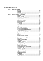
... not function and 'TRV' appears. MF4 (MULTI-FUNCTION 4 SWITCH) ➥ Selects 6 dB, 12 dB or 18 dB attenua- When a transverter is the preamp? AMP2" activates 16 dB high-gain pre- MF2 (MULTI-FUNCTION 2 SWITCH) METER ➥ Selects RF power (Po), SWR,...; Functions vary depending on the operating condition. AMP2" when receiving weak signals. Select "P. 1 PANEL DESCRIPTION ■ Front panel (continued) #3 #4 #5 #6 #7 #8 #9 $0 $1 $2 NSCEIVER 7700 MONITOR D DELAY NB NB RF DRIVE TX RX SPLIT LOCK 1.8 1 10 4 21 7 GENE 3.5 2 14 5 24 8 50 0 MP-W MW 7 3 18 6 28 9 F-INP ...
... not function and 'TRV' appears. MF4 (MULTI-FUNCTION 4 SWITCH) ➥ Selects 6 dB, 12 dB or 18 dB attenua- When a transverter is the preamp? AMP2" activates 16 dB high-gain pre- MF2 (MULTI-FUNCTION 2 SWITCH) METER ➥ Selects RF power (Po), SWR,...; Functions vary depending on the operating condition. AMP2" when receiving weak signals. Select "P. 1 PANEL DESCRIPTION ■ Front panel (continued) #3 #4 #5 #6 #7 #8 #9 $0 $1 $2 NSCEIVER 7700 MONITOR D DELAY NB NB RF DRIVE TX RX SPLIT LOCK 1.8 1 10 4 21 7 GENE 3.5 2 14 5 24 8 50 0 MP-W MW 7 3 18 6 28 9 F-INP ...
Instruction Manual
Page 23
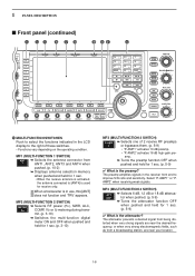
...A (or 250 V AC, 200 mA with 13.8 V outputs of a non-Icom linear amplifier. !9 T/R CONTROL JACK [RELAY] (p. 2-8) Connects to ground when transmitting to [ACC 2] pin 6, or when the transverter function is connected, [RX ANT- IN] @8 RECEIVE ANTENNA OUT [RX ANT- ...] must be deactivated and shorted by voltage applied to control an external unit, such as a non-Icom linear amplifier. Connected in total) _ + _ @6 TRANSVERTER CONNECTOR [X-VERTER] (p. 2-6) External transverter input/output connector. 1 PANEL DESCRIPTION !5 S/P DIF INPUT TERMINAL [S/P DIF- No adjustment is required ...
...A (or 250 V AC, 200 mA with 13.8 V outputs of a non-Icom linear amplifier. !9 T/R CONTROL JACK [RELAY] (p. 2-8) Connects to ground when transmitting to [ACC 2] pin 6, or when the transverter function is connected, [RX ANT- IN] @8 RECEIVE ANTENNA OUT [RX ANT- ...] must be deactivated and shorted by voltage applied to control an external unit, such as a non-Icom linear amplifier. Connected in total) _ + _ @6 TRANSVERTER CONNECTOR [X-VERTER] (p. 2-6) External transverter input/output connector. 1 PANEL DESCRIPTION !5 S/P DIF INPUT TERMINAL [S/P DIF- No adjustment is required ...
Instruction Manual
Page 27
...; Required connections 2-5 D Front panel 2-5 D Rear panel 2-5 ■ Advanced connections 2-6 D Front panel 2-6 D Rear panel-1 2-6 D Rear panel-2 2-7 ■ Linear amplifier connections 2-8 D Connecting the IC-PW1/EURO 2-8 D Connecting a non-Icom linear amplifier 2-8 ■ Transverter jack information 2-9 ■ FSK and AFSK (SSTV) connections 2-9 ■ Microphone connector information 2-10 ■ Microphones (options 2-10 D SM-20 2-10 D HM-36...
...; Required connections 2-5 D Front panel 2-5 D Rear panel 2-5 ■ Advanced connections 2-6 D Front panel 2-6 D Rear panel-1 2-6 D Rear panel-2 2-7 ■ Linear amplifier connections 2-8 D Connecting the IC-PW1/EURO 2-8 D Connecting a non-Icom linear amplifier 2-8 ■ Transverter jack information 2-9 ■ FSK and AFSK (SSTV) connections 2-9 ■ Microphone connector information 2-10 ■ Microphones (options 2-10 D SM-20 2-10 D HM-36...
Instruction Manual
Page 32
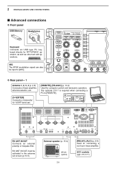
... RTTY/PSK DRIVE COMP MONI GAIN VOX GAIN D Rear panel- 1 Antenna 1, 2, 3, 4 (p. 2-8) Connects a linear amplifier, antenna selector, etc. [X-VERTER] Connects a transverter for V/UHF band use. [REMOTE], [RS-232C] (p. 14-2) Used for connecting a non-Icom linear amplifier. ANT 1 ANT 2 ANT 3 ANT 4 E X T- 2 INSTALLATION AND CONNECTIONS ■ Advanced connections D Front panel USB-Memory Headphones Keyboard Connects...
... RTTY/PSK DRIVE COMP MONI GAIN VOX GAIN D Rear panel- 1 Antenna 1, 2, 3, 4 (p. 2-8) Connects a linear amplifier, antenna selector, etc. [X-VERTER] Connects a transverter for V/UHF band use. [REMOTE], [RS-232C] (p. 14-2) Used for connecting a non-Icom linear amplifier. ANT 1 ANT 2 ANT 3 ANT 4 E X T- 2 INSTALLATION AND CONNECTIONS ■ Advanced connections D Front panel USB-Memory Headphones Keyboard Connects...
Instruction Manual
Page 35
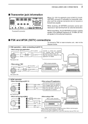
... port, speaker jack, microphone jack and line IN/OUT jack, etc. While receiving, [X-VERTER] connector can be activated as signals for the external transverter. ■ FSK and AFSK (SSTV) connections To connect a TNC or scan converter, etc., refer to pin 6 of [ACC 2], the [XVERTER... frequency at -20 dBm (22 mV) as an input terminal from an external transverter. While transmitting, the [X-VERTER] connector outputs signals of the PC 183 67 SEND PTT application for transverter operation and the antenna connectors do not receive or transmit any signals. 2 INSTALLATION AND...
... port, speaker jack, microphone jack and line IN/OUT jack, etc. While receiving, [X-VERTER] connector can be activated as signals for the external transverter. ■ FSK and AFSK (SSTV) connections To connect a TNC or scan converter, etc., refer to pin 6 of [ACC 2], the [XVERTER... frequency at -20 dBm (22 mV) as an input terminal from an external transverter. While transmitting, the [X-VERTER] connector outputs signals of the PC 183 67 SEND PTT application for transverter operation and the antenna connectors do not receive or transmit any signals. 2 INSTALLATION AND...
Instruction Manual
Page 168
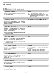
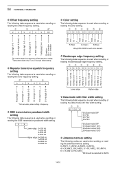
...Normal : Key open/close = Mark/Space • Reverse : Key open/close = Space/Mark PSK Tone Frequency Selects the desired PSK tone frequency for the transverter operation within 0.000 to [ACC2] pin 6. tion condition when 2 to 13.8 V DC is selected, Mark and Space are 3 selectable values: 170, ...Hz) 170 Hz is automatically selected when the internal RTTY decoder is used . 2125 170 RTTY Keying Polarity Selects the RTTY keying polarity. Transverter Offset Sets the desired offset frequency for the PSK reception from 1000, 1500 and 2000 Hz. (default: 1500 Hz) 1500 SPEECH Language ...
...Normal : Key open/close = Mark/Space • Reverse : Key open/close = Space/Mark PSK Tone Frequency Selects the desired PSK tone frequency for the transverter operation within 0.000 to [ACC2] pin 6. tion condition when 2 to 13.8 V DC is selected, Mark and Space are 3 selectable values: 170, ...Hz) 170 Hz is automatically selected when the internal RTTY decoder is used . 2125 170 RTTY Keying Polarity Selects the RTTY keying polarity. Transverter Offset Sets the desired offset frequency for the PSK reception from 1000, 1500 and 2000 Hz. (default: 1500 Hz) 1500 SPEECH Language ...
Instruction Manual
Page 193
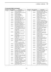
...details) Send/read split lock set (0=OFF, 1=ON) Send/read tuner auto start set (0=OFF, 1=ON) Send/read PTT tune set (0=OFF, 1=ON) Send/read transverter set (0=OFF, 1=15 min., 2=30 min., 3=60 min.) Set/read screen saver type (0=Bound, 1=Rotation, 2=Twist) Send/read output signal setting for external display... setting (0=OFF, 1=ON) Send/read manual notch width pop-up indication setting (0=OFF, 1=ON) Send/read screen saver set (0=OFF, 1=ON) Send/read transverter offset (see p. 14-9 for details) Send/read date (20000101=1st Jan. 2000 to 20991231=31st Dec. 2099) Send/read time (0000=00:00 to ...
...details) Send/read split lock set (0=OFF, 1=ON) Send/read tuner auto start set (0=OFF, 1=ON) Send/read PTT tune set (0=OFF, 1=ON) Send/read transverter set (0=OFF, 1=15 min., 2=30 min., 3=60 min.) Set/read screen saver type (0=Bound, 1=Rotation, 2=Twist) Send/read output signal setting for external display... setting (0=OFF, 1=ON) Send/read manual notch width pop-up indication setting (0=OFF, 1=ON) Send/read screen saver set (0=OFF, 1=ON) Send/read transverter offset (see p. 14-9 for details) Send/read date (20000101=1st Jan. 2000 to 20991231=31st Dec. 2099) Send/read time (0000=00:00 to ...
Instruction Manual
Page 198
... Hz 3=500 Hz Higher edge: 0=2500 Hz 1=2700 Hz 2=2800 Hz 3=2900 Hz D Data mode with filter width setting. Fix to enter for transverter offset frequency setting. †Transverter offset only; qwerty X XXXXXXXXXXX Lower edge Higher edge Fixed digit: 0* Fixed digit: 0* 100Hz digit: 0-2 10 Hz digit: 0-9 1 Hz digit: 0-9 0.1 Hz digit: 0-9 1 kHz: 0-9 100...
... Hz 3=500 Hz Higher edge: 0=2500 Hz 1=2700 Hz 2=2800 Hz 3=2900 Hz D Data mode with filter width setting. Fix to enter for transverter offset frequency setting. †Transverter offset only; qwerty X XXXXXXXXXXX Lower edge Higher edge Fixed digit: 0* Fixed digit: 0* 100Hz digit: 0-2 10 Hz digit: 0-9 1 Hz digit: 0-9 0.1 Hz digit: 0-9 1 kHz: 0-9 100...