Instruction Manual
Page 2
... RADIATORS This equipment has been tested and found to European versions for the IC-7700. TRADEMARKS Icom, Icom Inc. These limits are registered trademarks of the following measures: • Reorient or relocate the receiving antenna. • Increase the separation between the equipment and receiver. • Connect the equipment into the design of your radio of choice...
... RADIATORS This equipment has been tested and found to European versions for the IC-7700. TRADEMARKS Icom, Icom Inc. These limits are registered trademarks of the following measures: • Reorient or relocate the receiving antenna. • Increase the separation between the equipment and receiver. • Connect the equipment into the design of your radio of choice...

Instruction Manual
Page 6
...D Editing a memory keyer 4-9 D Contest number set mode 4-10 D Keyer set mode 4-11 ■ Operating RTTY (FSK 4-13 D Convenient functions for receive 4-14 D About RTTY reverse mode 4-14 D Twin peak filter 4-14 D Functions for the RTTY decoder indication 4-15 D Setting the decoder threshold level 4-15...4-16 D Editing RTTY memory 4-17 D RTTY decode set mode 4-18 D Data saving 4-20 ■ Operating PSK 4-21 D Convenient functions for receive 4-22 D About BPSK and QPSK modes 4-22 D Functions for the PSK decoder indication 4-23 D Setting the decoder threshold level 4-23 D PSK memory...
...D Editing a memory keyer 4-9 D Contest number set mode 4-10 D Keyer set mode 4-11 ■ Operating RTTY (FSK 4-13 D Convenient functions for receive 4-14 D About RTTY reverse mode 4-14 D Twin peak filter 4-14 D Functions for the RTTY decoder indication 4-15 D Setting the decoder threshold level 4-15...4-16 D Editing RTTY memory 4-17 D RTTY decode set mode 4-18 D Data saving 4-20 ■ Operating PSK 4-21 D Convenient functions for receive 4-22 D About BPSK and QPSK modes 4-22 D Functions for the PSK decoder indication 4-23 D Setting the decoder threshold level 4-23 D PSK memory...
Instruction Manual
Page 7
... Section 5 Section 6 ■ Repeater operation 4-32 D Repeater access tone frequency setting 4-33 ■ Tone squelch operation 4-34 ■ Data mode (AFSK) operation 4-35 FUNCTIONS FOR RECEIVE ■ Spectrum scope screen 5-2 D Center mode 5-2 D Fixed mode 5-3 D Mini scope screen indication 5-4 D Scope set mode 5-4 ■ Preamplifier 5-9 ■ Attenuator 5-9 ■ RIT function 5-10 D RIT monitor...
... Section 5 Section 6 ■ Repeater operation 4-32 D Repeater access tone frequency setting 4-33 ■ Tone squelch operation 4-34 ■ Data mode (AFSK) operation 4-35 FUNCTIONS FOR RECEIVE ■ Spectrum scope screen 5-2 D Center mode 5-2 D Fixed mode 5-3 D Mini scope screen indication 5-4 D Scope set mode 5-4 ■ Preamplifier 5-9 ■ Attenuator 5-9 ■ RIT function 5-10 D RIT monitor...
Instruction Manual
Page 8
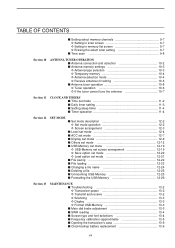
TABLE OF CONTENTS Section 7 Section 8 Section 9 VOICE RECORDER FUNCTIONS ■ About digital voice recorder 7-2 ■ Recording a received audio 7-3 D Basic recording 7-3 D One-touch recording 7-3 ■ Playing the recorded audio 7-4 D Basic playing 7-4 D One-...Sending a recorded message 7-8 D Transmit level setting 7-8 ■ Voice set mode 7-9 ■ Saving a voice memory into the USB-Memory 7-10 D Saving the received audio memory 7-10 D Saving the TX memory 7-10 MEMORY OPERATION ■ Memory channels 8-2 ■ Memory channel selection 8-2 D Using the ∫ / &#...
TABLE OF CONTENTS Section 7 Section 8 Section 9 VOICE RECORDER FUNCTIONS ■ About digital voice recorder 7-2 ■ Recording a received audio 7-3 D Basic recording 7-3 D One-touch recording 7-3 ■ Playing the recorded audio 7-4 D Basic playing 7-4 D One-...Sending a recorded message 7-8 D Transmit level setting 7-8 ■ Voice set mode 7-9 ■ Saving a voice memory into the USB-Memory 7-10 D Saving the received audio memory 7-10 D Saving the TX memory 7-10 MEMORY OPERATION ■ Memory channels 8-2 ■ Memory channel selection 8-2 D Using the ∫ / &#...
Instruction Manual
Page 9
... and selection 10-2 ■ Antenna memory settings 10-3 D Antenna type selection 10-3 D Temporary memory 10-4 D Antenna selection mode 10-4 D Receive antenna I/O setting 10-5 ■ Antenna tuner operation 10-6 D Tuner operation 10-6 D If the tuner cannot tune the antenna 10-7 Section 11...USB-Memory 12-25 ■ Formatting the USB-Memory 12-26 Section 13 MAINTENANCE ■ Troubleshooting 13-2 D Transceiver power 13-2 D Transmit and receive 13-2 D Scanning 13-3 D Display 13-3 D Format USB-Memory 13-3 ■ Main dial brake adjustment 13-3 ■ SWR reading 13-4...
... and selection 10-2 ■ Antenna memory settings 10-3 D Antenna type selection 10-3 D Temporary memory 10-4 D Antenna selection mode 10-4 D Receive antenna I/O setting 10-5 ■ Antenna tuner operation 10-6 D Tuner operation 10-6 D If the tuner cannot tune the antenna 10-7 Section 11...USB-Memory 12-25 ■ Formatting the USB-Memory 12-26 Section 13 MAINTENANCE ■ Troubleshooting 13-2 D Transceiver power 13-2 D Transmit and receive 13-2 D Scanning 13-3 D Display 13-3 D Format USB-Memory 13-3 ■ Main dial brake adjustment 13-3 ■ SWR reading 13-4...

Instruction Manual
Page 10
... D Data mode with filter width setting 14-10 D Antenna memory setting 14-10 Section 15 SPECIFICATIONS AND OPTIONS ■ Specifications 15-2 D General 15-2 D Transmitter 15-2 D Receiver 15-3 D Antenna tuner 15-3 ■ Options 15-4 Section 16 UPDATING THE FIRMWARE ■ General 16-2 ■ Caution 16-2 ■ Preparation 16-3 D Firmware and firm utility...
... D Data mode with filter width setting 14-10 D Antenna memory setting 14-10 Section 15 SPECIFICATIONS AND OPTIONS ■ Specifications 15-2 D General 15-2 D Transmitter 15-2 D Receiver 15-3 D Antenna tuner 15-3 ■ Options 15-4 Section 16 UPDATING THE FIRMWARE ■ General 16-2 ■ Caution 16-2 ■ Preparation 16-3 D Firmware and firm utility...
Instruction Manual
Page 12
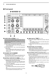
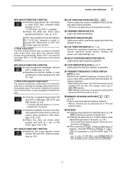
... internal power supply ON in use. ➥ Enters timer set mode. (p. 4-12) • A straight key jack is in first. w TRANSMIT SWITCH TRANSMIT Selects transmit or receive. • The [TX] indicator lights red while transmitting and the [RX] indicator lights green when the squelch is bypassed automatically after 20 sec. e ANTENNA TUNER...
... internal power supply ON in use. ➥ Enters timer set mode. (p. 4-12) • A straight key jack is in first. w TRANSMIT SWITCH TRANSMIT Selects transmit or receive. • The [TX] indicator lights red while transmitting and the [RX] indicator lights green when the squelch is bypassed automatically after 20 sec. e ANTENNA TUNER...
Instruction Manual
Page 13
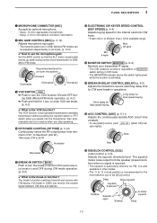
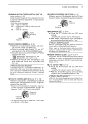
... mode. (p. 6-2) ✔ What is recommended for 1 sec. Deep Squelch threshold Noise squelch Shallow Squelch is particularly effective for an Icom microphone Increases Decreases Decreases Increases o VOX SWITCH VOX ➥ Push to 12 o'clock position is the VOX function? Long delay for ... GAIN CONTROL [MIC] (p. 3-12) Adjusts microphone input gain. • The transmit audio tone in SSB, AM and FM modes can monitor the receive signal between CW dots and dashes. !2 ELECTRONIC CW KEYER SPEED CONTROL [KEY SPEED] (p. 4-4) Adjusts keying speed for the internal electronic CW keyer....
... mode. (p. 6-2) ✔ What is recommended for 1 sec. Deep Squelch threshold Noise squelch Shallow Squelch is particularly effective for an Icom microphone Increases Decreases Decreases Increases o VOX SWITCH VOX ➥ Push to 12 o'clock position is the VOX function? Long delay for ... GAIN CONTROL [MIC] (p. 3-12) Adjusts microphone input gain. • The transmit audio tone in SSB, AM and FM modes can monitor the receive signal between CW dots and dashes. !2 ELECTRONIC CW KEYER SPEED CONTROL [KEY SPEED] (p. 4-4) Adjusts keying speed for the internal electronic CW keyer....
Instruction Manual
Page 15
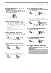
...LCD contrast. Push Dark Bright #2 AUTOMATIC TUNING SWITCH [AUTOTUNE] (p. 5-19) Turns the automatic tuning function ON and OFF in SSB. When receiving a weak signal, or receiving a signal with [COMP] OFF). 1 PANEL DESCRIPTION @3 RF GAIN CONTROL [RF] (outer control; Active in FM mode, or on ...in CW and AM modes. IMPORTANT! Push Monitor gain decreases Monitor gain increases @8 VOX GAIN CONTROL [VOX GAIN] (p. 6-2) Adjusts the transmit/receive switching threshold level for 1 sec. @5 DRIVE GAIN CONTROL [DRIVE] (p. 3-13) Adjusts the transmitter level at the driver stage. Push ...
...LCD contrast. Push Dark Bright #2 AUTOMATIC TUNING SWITCH [AUTOTUNE] (p. 5-19) Turns the automatic tuning function ON and OFF in SSB. When receiving a weak signal, or receiving a signal with [COMP] OFF). 1 PANEL DESCRIPTION @3 RF GAIN CONTROL [RF] (outer control; Active in FM mode, or on ...in CW and AM modes. IMPORTANT! Push Monitor gain decreases Monitor gain increases @8 VOX GAIN CONTROL [VOX GAIN] (p. 6-2) Adjusts the transmit/receive switching threshold level for 1 sec. @5 DRIVE GAIN CONTROL [DRIVE] (p. 3-13) Adjusts the transmitter level at the driver stage. Push ...
Instruction Manual
Page 16
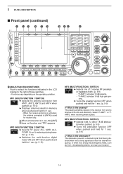
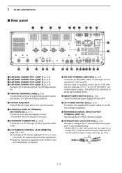
...➥ Turns the attenuator function OFF when pushed and held for 1 sec. (p. 5-9) ✔ What is the attenuator? AMP2" when receiving weak signals. AMP2" activates 16 dB high-gain pre- When a transverter is the preamp? AMP1" activates 10 dB preamp. • ... ANT2, ANT3 and ANT4 when pushed. (p. 10-2) ➥ Displays antenna selection memory when pushed and held for receive only. 1 PANEL DESCRIPTION ■ Front panel (continued) #3 #4 #5 #6 #7 #8 #9 $0 $1 $2 NSCEIVER 7700 MONITOR D DELAY NB NB RF DRIVE TX RX SPLIT LOCK 1.8 1 10 4 21 7 GENE 3.5 2 14 ...
...➥ Turns the attenuator function OFF when pushed and held for 1 sec. (p. 5-9) ✔ What is the attenuator? AMP2" when receiving weak signals. AMP2" activates 16 dB high-gain pre- When a transverter is the preamp? AMP1" activates 10 dB preamp. • ... ANT2, ANT3 and ANT4 when pushed. (p. 10-2) ➥ Displays antenna selection memory when pushed and held for receive only. 1 PANEL DESCRIPTION ■ Front panel (continued) #3 #4 #5 #6 #7 #8 #9 $0 $1 $2 NSCEIVER 7700 MONITOR D DELAY NB NB RF DRIVE TX RX SPLIT LOCK 1.8 1 10 4 21 7 GENE 3.5 2 14 ...
Instruction Manual
Page 17
...the general coverage band. ➥ Pushing the same key 2 or 3 times calls up other stacked frequencies in the band. (p. 3-4) • Icom's triple band stacking register memorizes 3 frequencies in each band. ➥ After pushing F-INPENT , enters a frequency or memory channel. This function is ... function. (p. 6-7) $1 MEMORY UP/DOWN SWITCHES ∫ / √ (p. 8-2) Push to produce a constant audio output level, even when the received signal strength varies dramatically. MF6 (MULTI-FUNCTION 6 SWITCH) COMP OFF WIDE ➥ Turns the speech compressor ON and OFF in FM mode. (pgs...
...the general coverage band. ➥ Pushing the same key 2 or 3 times calls up other stacked frequencies in the band. (p. 3-4) • Icom's triple band stacking register memorizes 3 frequencies in each band. ➥ After pushing F-INPENT , enters a frequency or memory channel. This function is ... function. (p. 6-7) $1 MEMORY UP/DOWN SWITCHES ∫ / √ (p. 8-2) Push to produce a constant audio output level, even when the received signal strength varies dramatically. MF6 (MULTI-FUNCTION 6 SWITCH) COMP OFF WIDE ➥ Turns the speech compressor ON and OFF in FM mode. (pgs...

Instruction Manual
Page 18
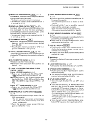
RTTY/PSK ➥ Switches between transmit frequency and receive frequency when the split frequency function is ON. (p. 6-6) $6 MEMORY WRITE SWITCH MW (p. 8-3) Stores the selected readout frequency and operating mode into the displayed ...RTTY and PSK mode. ➥ Switches RTTY and RTTY-R (RTTY reverse) mode when pushed and held for 1 sec. 1 PANEL DESCRIPTION ■ Front panel (continued) $3 $4 $5 $6 $7 $8 $9 %0 %1 %2 NSCEIVER 7700 MONITOR D DELAY NB NB RF DRIVE TX RX SPLIT LOCK 1.8 1 10 4 21 7 GENE 3.5 2 14 5 24 8 50 0 MP-W MW 7 3 18 6 28 9 F-INP ENT MP-R V/M XFC A/B ...
RTTY/PSK ➥ Switches between transmit frequency and receive frequency when the split frequency function is ON. (p. 6-6) $6 MEMORY WRITE SWITCH MW (p. 8-3) Stores the selected readout frequency and operating mode into the displayed ...RTTY and PSK mode. ➥ Switches RTTY and RTTY-R (RTTY reverse) mode when pushed and held for 1 sec. 1 PANEL DESCRIPTION ■ Front panel (continued) $3 $4 $5 $6 $7 $8 $9 %0 %1 %2 NSCEIVER 7700 MONITOR D DELAY NB NB RF DRIVE TX RX SPLIT LOCK 1.8 1 10 4 21 7 GENE 3.5 2 14 5 24 8 50 0 MP-W MW 7 3 18 6 28 9 F-INP ENT MP-R V/M XFC A/B ...
Instruction Manual
Page 19
...TPF " appears when twin peak filter is in use . ➥ Push and hold for 1 sec. When pushed and held for 1 sec. to record the received signal until the recording is additionally announced when pushed and held for 1 sec. ^0 SPLIT SWITCH SPLIT (p. 6-6) ➥ Turns the split function ON and OFF...10149; Turns the spectrum scope screen ON when pushed and held for 1 sec. %4 VOICE MEMORY RECORD SWITCH REC (p. 7-3) ➥ Push to record the previous received signal for the preset time period. • The preset time period can be set in voice set mode. (p. 7-9) ➥ Push and hold for 1 ...
...TPF " appears when twin peak filter is in use . ➥ Push and hold for 1 sec. When pushed and held for 1 sec. to record the received signal until the recording is additionally announced when pushed and held for 1 sec. ^0 SPLIT SWITCH SPLIT (p. 6-6) ➥ Turns the split function ON and OFF...10149; Turns the spectrum scope screen ON when pushed and held for 1 sec. %4 VOICE MEMORY RECORD SWITCH REC (p. 7-3) ➥ Push to record the previous received signal for the preset time period. • The preset time period can be set in voice set mode. (p. 7-9) ➥ Push and hold for 1 ...
Instruction Manual
Page 20
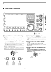
... DIGI-SEL NOTCH APF/TPF NOTCH RIT/∂TX RIT ∂TX CLEAR SPEECH CW PITCH SPLIT ^1 ^2 ^3 ^4 ^5 ^6 ^7 ^8 ^1 PASSBAND TUNING CONTROLS [TWIN-PBT] (p. 5-12) Adjusts the receiver's IF filter "passband width" via the DSP. • Passband width and shift frequency are available. ✔ What is the PBT control? The PBT function electronically...
... DIGI-SEL NOTCH APF/TPF NOTCH RIT/∂TX RIT ∂TX CLEAR SPEECH CW PITCH SPLIT ^1 ^2 ^3 ^4 ^5 ^6 ^7 ^8 ^1 PASSBAND TUNING CONTROLS [TWIN-PBT] (p. 5-12) Adjusts the receiver's IF filter "passband width" via the DSP. • Passband width and shift frequency are available. ✔ What is the PBT control? The PBT function electronically...
Instruction Manual
Page 21
...frequency to effectively eliminate unwanted tones. ^7 RIT/∂TX CONTROL [RIT/∂TX] (pgs. 5-10, 6-4) Shifts the receive and/or transmit frequency without shifting the transmit frequency. This is the RIT function? 1 PANEL DESCRIPTION ^5 MANUAL NOTCH FILTER CONTROL [NOTCH...] (outer control; Receiver incremental tuning (RIT) shifts the receive frequency without changing the transmit and/or receive frequency shown on the quick RIT/∂TX clear function setting (p. 12-15). &1 ∂TX ...
...frequency to effectively eliminate unwanted tones. ^7 RIT/∂TX CONTROL [RIT/∂TX] (pgs. 5-10, 6-4) Shifts the receive and/or transmit frequency without shifting the transmit frequency. This is the RIT function? 1 PANEL DESCRIPTION ^5 MANUAL NOTCH FILTER CONTROL [NOTCH...] (outer control; Receiver incremental tuning (RIT) shifts the receive frequency without changing the transmit and/or receive frequency shown on the quick RIT/∂TX clear function setting (p. 12-15). &1 ∂TX ...
Instruction Manual
Page 22
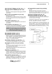
u EXTERNAL DISPLAY TERMINAL [EXT-DISPLAY] (p. 2-7) Connects to remotely control the IC-7700 without the optional CT-17, or for RTTY/PSK31 decoded signal output. Can be used ...CONNECTOR 2 [ANT 2] (p. 2-5) e ANTENNA CONNECTOR 3 [ANT 3] (p. 2-5) r ANTENNA CONNECTOR 4 [ANT 4] (p. 2-5) Accept a 50 Ω antenna with another Icom CI-V transceiver or receiver. !0 RS-232C TERMINAL [RS-232C] (p. 2-6) Connects an RS-232C cable, D-sub 9-pin to connect the IC-7700 to a PC through a LAN (Local Area Network). 1 PANEL DESCRIPTION ■ Rear panel q w e r t y u i o !0 ANT 1 ANT 2...
u EXTERNAL DISPLAY TERMINAL [EXT-DISPLAY] (p. 2-7) Connects to remotely control the IC-7700 without the optional CT-17, or for RTTY/PSK31 decoded signal output. Can be used ...CONNECTOR 2 [ANT 2] (p. 2-5) e ANTENNA CONNECTOR 3 [ANT 3] (p. 2-5) r ANTENNA CONNECTOR 4 [ANT 4] (p. 2-5) Accept a 50 Ω antenna with another Icom CI-V transceiver or receiver. !0 RS-232C TERMINAL [RS-232C] (p. 2-6) Connects an RS-232C cable, D-sub 9-pin to connect the IC-7700 to a PC through a LAN (Local Area Network). 1 PANEL DESCRIPTION ■ Rear panel q w e r t y u i o !0 ANT 1 ANT 2...
Instruction Manual
Page 23
.... !9 T/R CONTROL JACK [RELAY] (p. 2-8) Connects to ground when transmitting to control an external unit, such as a non-Icom linear amplifier. Transceiver mute control line (both transmit and receive) is also supported. @4 METER JACK [METER] (p. 2-7) Outputs a signal showing received signal strength, transmit output power, VSWR, ALC, speech compression, VD or ID level for external meter...
.... !9 T/R CONTROL JACK [RELAY] (p. 2-8) Connects to ground when transmitting to control an external unit, such as a non-Icom linear amplifier. Transceiver mute control line (both transmit and receive) is also supported. @4 METER JACK [METER] (p. 2-7) Outputs a signal showing received signal strength, transmit output power, VSWR, ALC, speech compression, VD or ID level for external meter...
Instruction Manual
Page 24
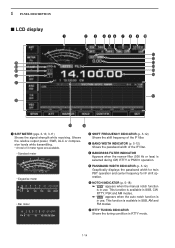
... or less) is in use . This function is in use . 1 PANEL DESCRIPTION ■ LCD display q @5 @4 @3 @2 @1 @0 w e r t y u i o !0 !1 !2 !3 !4 !5 !6 !7 !9 !8 q S/RF METER (pgs. 3-10, 3-11) Shows the signal strength while receiving. u RTTY TUNING INDICATOR Shows the tuning condition in SSB, AM and FM modes. t PASSBAND WIDTH INDICATOR (p. 5-12) Graphically displays the passband width for twin PBT...
... or less) is in use . This function is in use . 1 PANEL DESCRIPTION ■ LCD display q @5 @4 @3 @2 @1 @0 w e r t y u i o !0 !1 !2 !3 !4 !5 !6 !7 !9 !8 q S/RF METER (pgs. 3-10, 3-11) Shows the signal strength while receiving. u RTTY TUNING INDICATOR Shows the tuning condition in SSB, AM and FM modes. t PASSBAND WIDTH INDICATOR (p. 5-12) Graphically displays the passband width for twin PBT...
Instruction Manual
Page 30
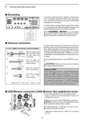
...correctly. Antenna SWR Each antenna is recommended before removing the USB-Memory* (p.12-25). The IC-7700 has an SWR meter to the USB connector. • Unmount operation is tuned for transmitting. or ... frequency range and SWR may be increased out-of critical importance, along with output power and receiver sensitivity. Strip the cable jacket and 10 mm (soft solder) tin the braid. Make sure... 1⁄16 in For radio communications, the antenna is not supplied by Icom) Connect the USB-Memory* to monitor the antenna SWR continuously. ■ USB-Memory connection (USB-Memory:...
...correctly. Antenna SWR Each antenna is recommended before removing the USB-Memory* (p.12-25). The IC-7700 has an SWR meter to the USB connector. • Unmount operation is tuned for transmitting. or ... frequency range and SWR may be increased out-of critical importance, along with output power and receiver sensitivity. Strip the cable jacket and 10 mm (soft solder) tin the braid. Make sure... 1⁄16 in For radio communications, the antenna is not supplied by Icom) Connect the USB-Memory* to monitor the antenna SWR continuously. ■ USB-Memory connection (USB-Memory:...
Instruction Manual
Page 31
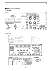
... RS-232C AC I /O 10MHz -10dBm Antenna 1, 2, 3, 4 (p. 2-4) [Example]: ANT1 for 1.8-18 MHz bands, ANT 2 for 21-28 MHz bands ANT3 for 50 MHz band, ANT 4 for receive antenna. NOTE: Attach the supplied antenna connector cap when no antenna or external equipment is changed in keyer set mode. (p. 4-12) Microphones (p. 2-10) Optional SM...
... RS-232C AC I /O 10MHz -10dBm Antenna 1, 2, 3, 4 (p. 2-4) [Example]: ANT1 for 1.8-18 MHz bands, ANT 2 for 21-28 MHz bands ANT3 for 50 MHz band, ANT 4 for receive antenna. NOTE: Attach the supplied antenna connector cap when no antenna or external equipment is changed in keyer set mode. (p. 4-12) Microphones (p. 2-10) Optional SM...


