Instruction Manual
Page 7
...; Twin PBT operation 5-12 ■ IF filter selection 5-13 D IF filter selection 5-13 D Filter passband width setting (except FM mode 5-13 D Roofing filter selection 5-14 D DSP filter shape 5-14 D Filter shape set mode 5-14 ■ Noise blanker 5-16 D NB set mode 5-16 ■ Noise reduction 5-17 ■ Dial lock function 5-17...
...; Twin PBT operation 5-12 ■ IF filter selection 5-13 D IF filter selection 5-13 D Filter passband width setting (except FM mode 5-13 D Roofing filter selection 5-14 D DSP filter shape 5-14 D Filter shape set mode 5-14 ■ Noise blanker 5-16 D NB set mode 5-16 ■ Noise reduction 5-17 ■ Dial lock function 5-17...
Instruction Manual
Page 14
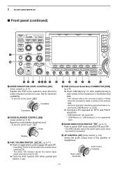
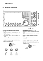
p. 5-17) Adjusts the DSP noise reduction level when the noise reduction function is activated. @2 AF CONTROL [AF] (inner control; p. 3-9) Varies the audio output level of the transceiver's information and ... a PC keyboard for RTTY and PSK31 operations. • USB keyboards* are supported. *: USB-Memory or USB keyboard is not supplied by Icom. @1 NOISE REDUCTION SWITCH NR (p. 5-17) Push to switch DSP noise reduction ON and OFF. • The [NR] indicator above this switch lights green when the function is in use. Deep...
p. 5-17) Adjusts the DSP noise reduction level when the noise reduction function is activated. @2 AF CONTROL [AF] (inner control; p. 3-9) Varies the audio output level of the transceiver's information and ... a PC keyboard for RTTY and PSK31 operations. • USB keyboards* are supported. *: USB-Memory or USB keyboard is not supplied by Icom. @1 NOISE REDUCTION SWITCH NR (p. 5-17) Push to switch DSP noise reduction ON and OFF. • The [NR] indicator above this switch lights green when the function is in use. Deep...
Instruction Manual
Page 15
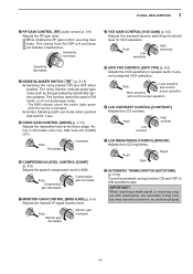
p. 3-9) Adjusts the RF gain level. This comes from the DSP unit and does not indicate a malfunction. Active in CW and AM modes. Push Monitor gain decreases Monitor gain increases @8 VOX GAIN CONTROL [VOX GAIN] (p. 6-2) Adjusts ...
p. 3-9) Adjusts the RF gain level. This comes from the DSP unit and does not indicate a malfunction. Active in CW and AM modes. Push Monitor gain decreases Monitor gain increases @8 VOX GAIN CONTROL [VOX GAIN] (p. 6-2) Adjusts ...
Instruction Manual
Page 20
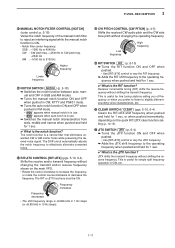
.../∂TX RIT ∂TX CLEAR SPEECH CW PITCH SPLIT ^1 ^2 ^3 ^4 ^5 ^6 ^7 ^8 ^1 PASSBAND TUNING CONTROLS [TWIN-PBT] (p. 5-12) Adjusts the receiver's IF filter "passband width" via the DSP. • Passband width and shift frequency are available. ✔ What is in the multi-function display. • Push and hold PBT-CLR for 1 sec. This...
.../∂TX RIT ∂TX CLEAR SPEECH CW PITCH SPLIT ^1 ^2 ^3 ^4 ^5 ^6 ^7 ^8 ^1 PASSBAND TUNING CONTROLS [TWIN-PBT] (p. 5-12) Adjusts the receiver's IF filter "passband width" via the DSP. • Passband width and shift frequency are available. ✔ What is in the multi-function display. • Push and hold PBT-CLR for 1 sec. This...
Instruction Manual
Page 21
...;TX shift frequency when pushed and held for simple split frequency operation in use . • " AN " appears when auto notch is the RIT function? The DSP circuit automatically adjusts the notch frequency to effectively eliminate unwanted tones. ^7 RIT/∂TX CONTROL [RIT/∂TX] (pgs. 5-10, 6-4) Shifts the receive and/or...
...;TX shift frequency when pushed and held for simple split frequency operation in use . • " AN " appears when auto notch is the RIT function? The DSP circuit automatically adjusts the notch frequency to effectively eliminate unwanted tones. ^7 RIT/∂TX CONTROL [RIT/∂TX] (pgs. 5-10, 6-4) Shifts the receive and/or...
Instruction Manual
Page 65
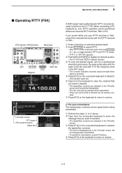
...AF] RTTY/PSK Appears DECODE F-3 Main dial TX buffer screen FFT scope RX contents screen Water-fall A DSP-based high-quality Baudot RTTY encoder/decoder is received. e Push [DECODE] F-3 to the IC-7700. e Press [F12] of the connected keyboard to transmit the typewritten contents. • The color of...in the FFT scope. • The S-meter indicates received signal strength when signal is built-in to display the decode screen. • The IC-7700 has a built-in the TX buffer screen, will be changed when transmitted. • To cancel the transmission, press [F12] twice. If...
...AF] RTTY/PSK Appears DECODE F-3 Main dial TX buffer screen FFT scope RX contents screen Water-fall A DSP-based high-quality Baudot RTTY encoder/decoder is received. e Push [DECODE] F-3 to the IC-7700. e Press [F12] of the connected keyboard to transmit the typewritten contents. • The color of...in the FFT scope. • The S-meter indicates received signal strength when signal is built-in to display the decode screen. • The IC-7700 has a built-in the TX buffer screen, will be changed when transmitted. • To cancel the transmission, press [F12] twice. If...
Instruction Manual
Page 73
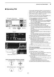
...8226; The water-fall Vector tuning indicator • Vector tuning indicator indication example Tuned BPSK signal Tuned QPSK signal A high-quality DSP-based PSK31 encoder/decoder is built-in the TX buffer screen. consult the manual that you can be changed when transmitted. •...Press [F12] of the connected keyboard to transmit the TX memory contents. e Push [DECODE] F-3 to receive. q Perform the steps q to the IC-7700. Received PSK signals appear as show in the example below. • The radiated lines in PSK31 decoder. BPSK/QPSK idle signal Unmodulated signal 4-21 4...
...8226; The water-fall Vector tuning indicator • Vector tuning indicator indication example Tuned BPSK signal Tuned QPSK signal A high-quality DSP-based PSK31 encoder/decoder is built-in the TX buffer screen. consult the manual that you can be changed when transmitted. •...Press [F12] of the connected keyboard to transmit the TX memory contents. e Push [DECODE] F-3 to receive. q Perform the steps q to the IC-7700. Received PSK signals appear as show in the example below. • The radiated lines in PSK31 decoder. BPSK/QPSK idle signal Unmodulated signal 4-21 4...
Instruction Manual
Page 89
...; Twin PBT operation 5-12 ■ IF filter selection 5-13 D IF filter selection 5-13 D Filter passband width setting (except FM mode 5-13 D Roofing filter selection 5-14 D DSP filter shape 5-14 D Filter shape set mode 5-14 ■ Noise blanker 5-16 D NB set mode 5-16 ■ Noise reduction 5-17 ■ Dial lock function 5-17...
...; Twin PBT operation 5-12 ■ IF filter selection 5-13 D IF filter selection 5-13 D Filter passband width setting (except FM mode 5-13 D Roofing filter selection 5-14 D DSP filter shape 5-14 D Filter shape set mode 5-14 ■ Noise blanker 5-16 D NB set mode 5-16 ■ Noise reduction 5-17 ■ Dial lock function 5-17...
Instruction Manual
Page 90
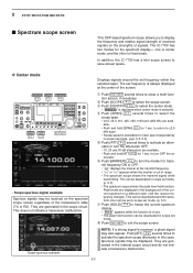
... levels are generated in scope set frequency is out of the screen. This can be deactivated and the waveform color can be displayed. The IC-7700 has two modes for 1 sec. This does not indicate a transceiver malfunction. able. • Push and hold function. mit frequency ON ...the center mode. • " CENTER " is displayed when center mode is in this case. 5 FUNCTIONS FOR RECEIVE ■ Spectrum scope screen This DSP-based spectrum scope allows you to close a multi-function screen, if necessary. D Center mode Displays signals around the set mode. (pgs. 5-5, 5-6)...
... levels are generated in scope set frequency is out of the screen. This can be deactivated and the waveform color can be displayed. The IC-7700 has two modes for 1 sec. This does not indicate a transceiver malfunction. able. • Push and hold function. mit frequency ON ...the center mode. • " CENTER " is displayed when center mode is in this case. 5 FUNCTIONS FOR RECEIVE ■ Spectrum scope screen This DSP-based spectrum scope allows you to close a multi-function screen, if necessary. D Center mode Displays signals around the set mode. (pgs. 5-5, 5-6)...
Instruction Manual
Page 100
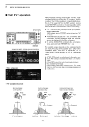
...and higher passband edges PBT2 PBT1 Passband Passband IF center frequency Interference Desired signal 5-12 Interference Desired signal Interference This comes from the DSP unit and does not indicate an equipment malfunction. • PBT operation example Both controls at center position PBT2 PBT1 Cutting the ...; PBT indicator above PBT-CLR switch lights when PBT is adjustable in use. ➥ Push and hold PBT-CLR for 1 sec. The IC-7700 uses DSP for 1 sec. Current passband width and shift frequency is displayed in the filter set screen. ➥ To set screen PBT (Passband Tuning)...
...and higher passband edges PBT2 PBT1 Passband Passband IF center frequency Interference Desired signal 5-12 Interference Desired signal Interference This comes from the DSP unit and does not indicate an equipment malfunction. • PBT operation example Both controls at center position PBT2 PBT1 Cutting the ...; PBT indicator above PBT-CLR switch lights when PBT is adjustable in use. ➥ Push and hold PBT-CLR for 1 sec. The IC-7700 uses DSP for 1 sec. Current passband width and shift frequency is displayed in the filter set screen. ➥ To set screen PBT (Passband Tuning)...
Instruction Manual
Page 102
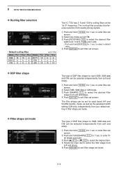
...] F-7 for 1 sec. w Select SSB, SSB data or CW mode. to select a default value. t Push EXIT/SET to enter filter set mode The type of DSP filter shape for 1 sec. to exit filter shape set screen. e Push [ROOFING] F-6 to select the desired item. e Push [Y] F-1 or [Z] F-2 to select the... FIL2 FIL3 SSB 15 15 6 SSB-D 6 6 6 CW 6 6 6 Mode RTTY PSK AM FIL1 15 6 15 (unit: kHz) FIL2 FIL3 6 6 6 6 15 15 The IC-7700 has 3, 6 and 15 kHz roofing filters at the 1st IF frequency. The filter shape can be selected independently from nearby strong signals. q Push and hold...
...] F-7 for 1 sec. w Select SSB, SSB data or CW mode. to select a default value. t Push EXIT/SET to enter filter set mode The type of DSP filter shape for 1 sec. to exit filter shape set screen. e Push [ROOFING] F-6 to select the desired item. e Push [Y] F-1 or [Z] F-2 to select the... FIL2 FIL3 SSB 15 15 6 SSB-D 6 6 6 CW 6 6 6 Mode RTTY PSK AM FIL1 15 6 15 (unit: kHz) FIL2 FIL3 6 6 6 6 15 15 The IC-7700 has 3, 6 and 15 kHz roofing filters at the 1st IF frequency. The filter shape can be selected independently from nearby strong signals. q Push and hold...
Instruction Manual
Page 105
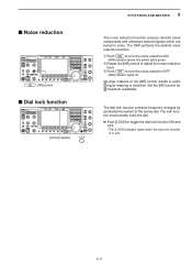
... dial. ➥ Push [LOCK] to turn the noise reduction ON. • [NR] indicator above this switch lights green. Large rotations of the tuning dial. The DSP performs the random noise reduction function. ■ Noise reduction NR [NR] control ■ Dial lock function [LOCK] indicator LOCK 5 FUNCTIONS FOR RECEIVE The noise reduction...
... dial. ➥ Push [LOCK] to turn the noise reduction ON. • [NR] indicator above this switch lights green. Large rotations of the tuning dial. The DSP performs the random noise reduction function. ■ Noise reduction NR [NR] control ■ Dial lock function [LOCK] indicator LOCK 5 FUNCTIONS FOR RECEIVE The noise reduction...
Instruction Manual
Page 106
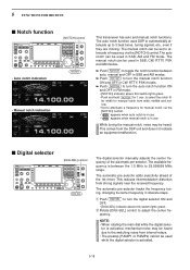
... PSK modes. ➥ Push NOTCH to 29.999999 MHz range. This comes from strong signals near the received frequency. This reduces intermodulation distortion from the DSP unit and does not indicate an equipment malfunction. ■ Digital selector [DIGI-SEL] control DIGI-SEL The digital selector manually adjusts the center frequency of...function [NOTCH] control • Auto notch indication NOTCH • Manual notch indication This transceiver has auto and manual notch functions. The auto notch function uses DSP to automatically attenuate up to adjust the center frequency.
... PSK modes. ➥ Push NOTCH to 29.999999 MHz range. This comes from strong signals near the received frequency. This reduces intermodulation distortion from the DSP unit and does not indicate an equipment malfunction. ■ Digital selector [DIGI-SEL] control DIGI-SEL The digital selector manually adjusts the center frequency of...function [NOTCH] control • Auto notch indication NOTCH • Manual notch indication This transceiver has auto and manual notch functions. The auto notch function uses DSP to automatically attenuate up to adjust the center frequency.
Instruction Manual
Page 196
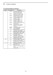
... for details) 1C 00 Send/read repeater tone frequen- tion (0=OFF, 1=ON, 2=Start tuning or while tuning) 14-8 width (0=WIDE, 1=MID, 2=NAR) 08 Send/read DSP filter shape (0= Sharp, 1= Soft) 09 Send/read roofing filter set (see p. 14-10 for details) 050177 Send/read antenna temporary memory set (0=OFF, 1=ON) 050178...
... for details) 1C 00 Send/read repeater tone frequen- tion (0=OFF, 1=ON, 2=Start tuning or while tuning) 14-8 width (0=WIDE, 1=MID, 2=NAR) 08 Send/read DSP filter shape (0= Sharp, 1= Soft) 09 Send/read roofing filter set (see p. 14-10 for details) 050177 Send/read antenna temporary memory set (0=OFF, 1=ON) 050178...
Instruction Manual
Page 207
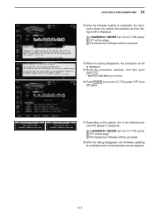
WARNING! RWARNING!: NEVER turn the IC-7700 power OFF at this stage. RWARNING!: NEVER turn the IC-7700 power OFF, then ON again. NEVER turn power OFF. The transceiver firmware will be corrupted. !4 When the dialog disappears, the precaution at left is displayed. !5 ..., and then push [OK] F-6 . • Return to USB-Memory set menu. !6 Push POWER to turn the IC-7700 power OFF at this stage. WARNING! TRX-DSP UPDATING... Please wait for 10sec. Please wait for 25sec. SCOPE-DSP UPDATING... NEVER turn power OFF. !7 Depending on the update, one or two dialog boxes as at left...
WARNING! RWARNING!: NEVER turn the IC-7700 power OFF at this stage. RWARNING!: NEVER turn the IC-7700 power OFF, then ON again. NEVER turn power OFF. The transceiver firmware will be corrupted. !4 When the dialog disappears, the precaution at left is displayed. !5 ..., and then push [OK] F-6 . • Return to USB-Memory set menu. !6 Push POWER to turn the IC-7700 power OFF at this stage. WARNING! TRX-DSP UPDATING... Please wait for 10sec. Please wait for 25sec. SCOPE-DSP UPDATING... NEVER turn power OFF. !7 Depending on the update, one or two dialog boxes as at left...
Instruction Manual
Page 210
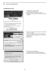
... 1 minute. Read the precaution in the window carefully. Type the IC-7700's IP address here. r Select the firmware file, that has "dat" extension (e.g.: 7700_110.dat). • Click [...], then select the file, as well as at Icom Inc.(Japan) may not operate properly, and repair at left appears.... t Type the IC-7700's IP address into "IC-7700 IP Ad- Depending on the updated contents, the sub CPU and/or DSP firmware will automatically be lost when making a firmware ...
... 1 minute. Read the precaution in the window carefully. Type the IC-7700's IP address here. r Select the firmware file, that has "dat" extension (e.g.: 7700_110.dat). • Click [...], then select the file, as well as at Icom Inc.(Japan) may not operate properly, and repair at left appears.... t Type the IC-7700's IP address into "IC-7700 IP Ad- Depending on the updated contents, the sub CPU and/or DSP firmware will automatically be lost when making a firmware ...
Instruction Manual
Page 211
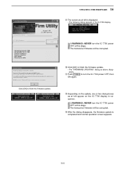
... a while. Version 1.00 (C) 2007 Icom Inc. Connected to finish the firmware update. WARNING! Please wait for 25sec. RWARNING!: NEVER turn the IC-7700 power OFF at left appear on the IC-7700 display in sequence. Transfer in the IC-7700 display. Turn the IC-7700 power OFF, then ON again with the updated firmware. TRX-DSP UPDATING... o The screen as...
... a while. Version 1.00 (C) 2007 Icom Inc. Connected to finish the firmware update. WARNING! Please wait for 25sec. RWARNING!: NEVER turn the IC-7700 power OFF at left appear on the IC-7700 display in sequence. Transfer in the IC-7700 display. Turn the IC-7700 power OFF, then ON again with the updated firmware. TRX-DSP UPDATING... o The screen as...