
Instruction Manual
Page 1
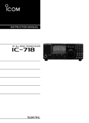
Operation is subject to the following two conditions: (1) This device may not cause harmful interference, and (2) this device must accept any interference received, including interference that may cause undesired operation. INSTRUCTION MANUAL HF ALL BAND TRANSCEIVER i718 This device complies with Part 15 of the FCC rules.
Operation is subject to the following two conditions: (1) This device may not cause harmful interference, and (2) this device must accept any interference received, including interference that may cause undesired operation. INSTRUCTION MANUAL HF ALL BAND TRANSCEIVER i718 This device complies with Part 15 of the FCC rules.
Instruction Manual
Page 2
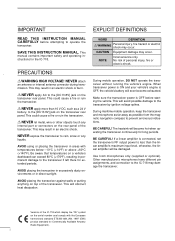
...extended periods. No risk of the transceiver. This will be damaged. Use Icom microphones only (supplied or optional). R NEVER apply AC to the [DC13.8V] jack on the transceiver rear panel. During mobile operation, DO NOT operate the transceiver without running the vehicle's engine. PRECAUTIONS...otherwise, the linear amplifier will avoid possible damage to the IC-718 may result in an electric shock. This will soon become hot when operating the transceiver continuously for the IC-718. EXPLICIT DEFINITIONS WORD DEFINITION R WARNING Personal injury, fire hazard or ...
...extended periods. No risk of the transceiver. This will be damaged. Use Icom microphones only (supplied or optional). R NEVER apply AC to the [DC13.8V] jack on the transceiver rear panel. During mobile operation, DO NOT operate the transceiver without running the vehicle's engine. PRECAUTIONS...otherwise, the linear amplifier will avoid possible damage to the IC-718 may result in an electric shock. This will soon become hot when operating the transceiver continuously for the IC-718. EXPLICIT DEFINITIONS WORD DEFINITION R WARNING Personal injury, fire hazard or ...

Instruction Manual
Page 3
... set mode items 42-43 s Initial set mode items 44-47 9 INSTALLATION AND CONNECTIONS ....... 48 - 51 s Opening the transceiver's case 48 s Optional bracket and carrying handle 48 s CR-338 HIGH STABILITY CRYSTAL UNIT .......... 49 s UT-102 VOICE SYNTHESIZER...CONTROL COMMAND 57 - 58 s Remote jack (CI-V) information 57 14 INTERNAL VIEWS 59 s Top view 59 s Bottom view 59 SUPPLIED ACCESSORIES q w The transceiver comes with the following accessories. 1 TABLE OF CONTENTS IMPORTANT i EXPLICIT DEFINITIONS i PRECAUTIONS i 1 TABLE OF CONTENTS 1 SUPPLIED ACCESSORIES 1 2 PANEL DESCRIPTION 2...
... set mode items 42-43 s Initial set mode items 44-47 9 INSTALLATION AND CONNECTIONS ....... 48 - 51 s Opening the transceiver's case 48 s Optional bracket and carrying handle 48 s CR-338 HIGH STABILITY CRYSTAL UNIT .......... 49 s UT-102 VOICE SYNTHESIZER...CONTROL COMMAND 57 - 58 s Remote jack (CI-V) information 57 14 INTERNAL VIEWS 59 s Top view 59 s Bottom view 59 SUPPLIED ACCESSORIES q w The transceiver comes with the following accessories. 1 TABLE OF CONTENTS IMPORTANT i EXPLICIT DEFINITIONS i PRECAUTIONS i 1 TABLE OF CONTENTS 1 SUPPLIED ACCESSORIES 1 2 PANEL DESCRIPTION 2...
Instruction Manual
Page 8
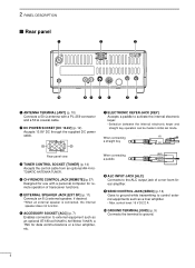
...and a 50 Ω coaxial cable. When connecting a paddle (dot) (com) (dash) i ALC INPUT JACK [ALC] Connects to the ALC output jack of transceiver functions. u ELECTRONIC KEYER JACK [KEY] Accepts a paddle to ground. 6 t EXTERNAL SPEAKER JACK [EXT SP] (p. 11) Connects an 8 Ω external ...ACC] (p. 7) Enables connection to control external equipments such as an optional AT-180 AUTOMATIC ANTENNA TUNER, a TNC for remote operation of a non-Icom linear amplifier. control level: 16 V DC/2 A !0 GROUND TERMINAL [GND] (p. 9) Connects the terminal to activate the internal electronic ...
...and a 50 Ω coaxial cable. When connecting a paddle (dot) (com) (dash) i ALC INPUT JACK [ALC] Connects to the ALC output jack of transceiver functions. u ELECTRONIC KEYER JACK [KEY] Accepts a paddle to ground. 6 t EXTERNAL SPEAKER JACK [EXT SP] (p. 11) Connects an 8 Ω external ...ACC] (p. 7) Enables connection to control external equipments such as an optional AT-180 AUTOMATIC ANTENNA TUNER, a TNC for remote operation of a non-Icom linear amplifier. control level: 16 V DC/2 A !0 GROUND TERMINAL [GND] (p. 9) Connects the terminal to activate the internal electronic ...
Instruction Manual
Page 11
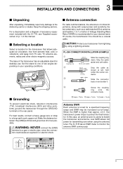
...shown at left. Soft solder the center conductor. When the SWR is useful to match the transceiver and antenna. The IC-718 has an SWR meter to the delivering carrier or dealer. 3 INSTALLATION AND CONNECTIONS s Unpacking ... terminal to a long earth-sunk copper rod. In this case, an antenna tuner is higher than approx. 2.0:1, the transceiver's power drops to one of two angles depending on p. 1 of Voltage Standing Wave Ratio (VSWR) is recommended for ... be increased out-of critical importance, along with the IC-718, see 'Supplied accessories' on your operating conditions.
...shown at left. Soft solder the center conductor. When the SWR is useful to match the transceiver and antenna. The IC-718 has an SWR meter to the delivering carrier or dealer. 3 INSTALLATION AND CONNECTIONS s Unpacking ... terminal to a long earth-sunk copper rod. In this case, an antenna tuner is higher than approx. 2.0:1, the transceiver's power drops to one of two angles depending on p. 1 of Voltage Standing Wave Ratio (VSWR) is recommended for ... be increased out-of critical importance, along with the IC-718, see 'Supplied accessories' on your operating conditions.
Instruction Manual
Page 13
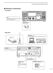
... (p. 55) SP-21, etc 11 ACC SOCKETS (p. 7) [SEND], [ALC] (p. 14) Used for computer control and transceive operation. 3 INSTALLATION AND CONNECTIONS s Advanced connections • Front panel MIC The AFSK modulation signal can be input from [MIC]. (p. 33) IC-718 MODE FIL TS PWR AF RF/SQL RIT SHIFT MIC PHONES LOCK 1 2 3 V/M A=B A/B 4 5 6 MW M - CL ∫... ∫ HEADPHONES • Rear panel AH-4 (p. 55) with AH-2b or long wire ANTENNA (p. 13) Connects a liner amprifier, etc. [REMOTE] (p. 57) Used for connecting a non-Icom linear amplifier.
... (p. 55) SP-21, etc 11 ACC SOCKETS (p. 7) [SEND], [ALC] (p. 14) Used for computer control and transceive operation. 3 INSTALLATION AND CONNECTIONS s Advanced connections • Front panel MIC The AFSK modulation signal can be input from [MIC]. (p. 33) IC-718 MODE FIL TS PWR AF RF/SQL RIT SHIFT MIC PHONES LOCK 1 2 3 V/M A=B A/B 4 5 6 MW M - CL ∫... ∫ HEADPHONES • Rear panel AH-4 (p. 55) with AH-2b or long wire ANTENNA (p. 13) Connects a liner amprifier, etc. [REMOTE] (p. 57) Used for connecting a non-Icom linear amplifier.
Instruction Manual
Page 16
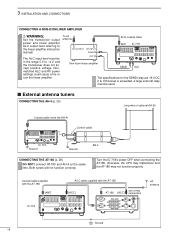
... amplifier. 3 INSTALLATION AND CONNECTIONS CONNECTING A NON-ICOM LINER AMPLIFIER R WARNING: Set the transceiver output power and linear amplifier ALC output level referring to -4 V, and the transceiver does not accept positive voltage. connect AT-180 and AH-4 at the same time. Turn the IC-718's power OFF when connecting the AT-180, otherwise, the...
... amplifier. 3 INSTALLATION AND CONNECTIONS CONNECTING A NON-ICOM LINER AMPLIFIER R WARNING: Set the transceiver output power and linear amplifier ALC output level referring to -4 V, and the transceiver does not accept positive voltage. connect AT-180 and AH-4 at the same time. Turn the IC-718's power OFF when connecting the AT-180, otherwise, the...
Instruction Manual
Page 17
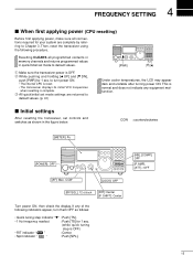
... indicator " RIT " : Center. • Split indicator " " : Push [SPL]. [NB], [COMP]: OFF [P.AMP], [ATT],: OFF 15 q Make sure the transceiver power is normal and does not indicate any of the following procedure. e All quick/initial set controls and switches as follows: • Quick tuning step...for your system are returned to turn them OFF as shown in quick/initial set mode to default values. s Initial settings After resetting the transceiver, set mode settings are complete by referring to Chapter 3. to default values. (p. 41) [PWR] √ [√] [∫] Under ...
... indicator " RIT " : Center. • Split indicator " " : Push [SPL]. [NB], [COMP]: OFF [P.AMP], [ATT],: OFF 15 q Make sure the transceiver power is normal and does not indicate any of the following procedure. e All quick/initial set controls and switches as follows: • Quick tuning step...for your system are returned to turn them OFF as shown in quick/initial set mode to default values. s Initial settings After resetting the transceiver, set mode settings are complete by referring to Chapter 3. to default values. (p. 41) [PWR] √ [√] [∫] Under ...
Instruction Manual
Page 19
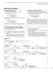
...- w Select the desired operating mode with keypad The transceiver has a keypad for the kHz digits. •To set to 21.025 MHz 2 1 A=B V/M NR 0 ANF 2 A=B 5 M=CL F-INP ENT •To set to select the desired ham band. • For general coverage receiver use The IC-718 has a general coverage receiver band. 4 FREQUENCY SETTING s Frequency...
...- w Select the desired operating mode with keypad The transceiver has a keypad for the kHz digits. •To set to 21.025 MHz 2 1 A=B V/M NR 0 ANF 2 A=B 5 M=CL F-INP ENT •To set to select the desired ham band. • For general coverage receiver use The IC-718 has a general coverage receiver band. 4 FREQUENCY SETTING s Frequency...
Instruction Manual
Page 29
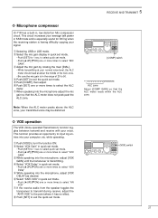
... DX'ing when the receiving station is transmitting. q Push [VOX] to input log entries into the microphone, adjust [VOX GAIN] until the transceiver is having difficulty copying your transmited voice may be distorted. ˛ [COMP] switch ALC zone Adjust [COMP GAIN] so that the...above the ALC zone, your signal. This function provides an opportunity to turn the function ON. 5 RECEIVE AND TRANSMIT ˛ ˛ ï Microphone compressor IC-718 has a built-in quick set mode. • Push [SET] for 1 sec. u When speaking into the microphone, adjust [VOX DELAY] as desired. ...
... DX'ing when the receiving station is transmitting. q Push [VOX] to input log entries into the microphone, adjust [VOX GAIN] until the transceiver is having difficulty copying your transmited voice may be distorted. ˛ [COMP] switch ALC zone Adjust [COMP GAIN] so that the...above the ALC zone, your signal. This function provides an opportunity to turn the function ON. 5 RECEIVE AND TRANSMIT ˛ ˛ ï Microphone compressor IC-718 has a built-in quick set mode. • Push [SET] for 1 sec. u When speaking into the microphone, adjust [VOX DELAY] as desired. ...
Instruction Manual
Page 30
...through " if the SWR is higher than 3:1 after 20 sec. Although termed "through inhibit," the tuner will be damage both the transceiver and the antenna tuner. CONVENIENT • Tuner sensitive condition If you want to turn power OFF. Once the tuner matches an antenna...TUNER is helpful. Therefore, manual tuning is emitted, and " " blinks; NOTE: NEVER select "4" (AH-4 AUTOMATIC ANTENNA TUNER), otherwise the transceiver transmits automatically when turning the power ON. This will not be tuned correctly. If the tuner cannot reduce the SWR to the connected antenna ...
...through " if the SWR is higher than 3:1 after 20 sec. Although termed "through inhibit," the tuner will be damage both the transceiver and the antenna tuner. CONVENIENT • Tuner sensitive condition If you want to turn power OFF. Once the tuner matches an antenna...TUNER is helpful. Therefore, manual tuning is emitted, and " " blinks; NOTE: NEVER select "4" (AH-4 AUTOMATIC ANTENNA TUNER), otherwise the transceiver transmits automatically when turning the power ON. This will not be tuned correctly. If the tuner cannot reduce the SWR to the connected antenna ...
Instruction Manual
Page 31
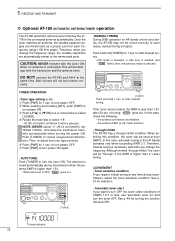
... frequency. TUNER OPERATION Tuning is turned ON in an HF band. • The IC-718 will not transmit outside of the operating frequency. y Push [PWR] for 1 sec. The tuner and transceiver will tune all frequencies 3.5 to turn power OFF. Note that the AH-4 cannot tune...Tuning indicator; w Push and hold [TUNER]" operation and activates first transmission on the transceiver directly. 5 RECEIVE AND TRANSMIT ï Optional AH-4 AUTOMATIC ANTENNA TUNER operation The AH-4 matches the IC-718 to turn power ON again. • MANUAL TUNING q Set the desired frequency in initial set...
... frequency. TUNER OPERATION Tuning is turned ON in an HF band. • The IC-718 will not transmit outside of the operating frequency. y Push [PWR] for 1 sec. The tuner and transceiver will tune all frequencies 3.5 to turn power OFF. Note that the AH-4 cannot tune...Tuning indicator; w Push and hold [TUNER]" operation and activates first transmission on the transceiver directly. 5 RECEIVE AND TRANSMIT ï Optional AH-4 AUTOMATIC ANTENNA TUNER operation The AH-4 matches the IC-718 to turn power ON again. • MANUAL TUNING q Set the desired frequency in initial set...

Instruction Manual
Page 37
..." blinks. w Push [CH] to exit memory CH select mode. in each memory channel as scan Yes edges for programmed scan. 6 MEMORY OPERATION s Memory channels The transceiver has 101 memory channels.
..." blinks. w Push [CH] to exit memory CH select mode. in each memory channel as scan Yes edges for programmed scan. 6 MEMORY OPERATION s Memory channels The transceiver has 101 memory channels.
Instruction Manual
Page 49
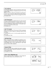
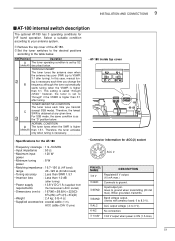
... to other Icom HF transceivers or receivers. on operating mode independently. The default is oF (off ). • OPTION Filter When an optional IF filer is installed, this selection expands filter and filter selection (W/N) key combination on the IC-718 automatically changes those of connected transceivers (or receivers) and vice versa. The IC-718's address...
... to other Icom HF transceivers or receivers. on operating mode independently. The default is oF (off ). • OPTION Filter When an optional IF filer is installed, this selection expands filter and filter selection (W/N) key combination on the IC-718 automatically changes those of connected transceivers (or receivers) and vice versa. The IC-718's address...
Instruction Manual
Page 50
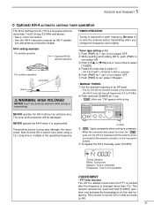
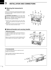
...top cover. s Optional bracket and carrying handle D Mounting bracket An optional IC-MB5 MOBILE MOUNTING BRACKET is available to install the radio under a table, on the transceiver. 9 INSTALLATION AND CONNECTIONS s Opening the transceiver's case Follow the case and cover opening procedures shown here when you to .... q Remove the 5 screws from the top of the transceiver and 4 screws from the bottom of electric shock and/or equipment damage. Otherwise, there is approx. 3.80kg. CAUTION: DISCONNECT the DC power cable from the IC-718 before performing any work on a wall, in mind that the...
...top cover. s Optional bracket and carrying handle D Mounting bracket An optional IC-MB5 MOBILE MOUNTING BRACKET is available to install the radio under a table, on the transceiver. 9 INSTALLATION AND CONNECTIONS s Opening the transceiver's case Follow the case and cover opening procedures shown here when you to .... q Remove the 5 screws from the top of the transceiver and 4 screws from the bottom of electric shock and/or equipment damage. Otherwise, there is approx. 3.80kg. CAUTION: DISCONNECT the DC power cable from the IC-718 before performing any work on a wall, in mind that the...
Instruction Manual
Page 53
... higher (default) than 3:1. Therefore, the tuner activates only when tuning is higher than 1.0 dB (after tuning) • Power supply : 13.8 V DC/1 A (supplied from requirements the transceiver's ACC socket) • Dimensions (mm/in) : 167(W) × 58.6(H) × 225(D) 69⁄16(W) × 25⁄17(H) × 87⁄8(D) • Weight : 2.4 kg; 5 lb...
... higher (default) than 3:1. Therefore, the tuner activates only when tuning is higher than 1.0 dB (after tuning) • Power supply : 13.8 V DC/1 A (supplied from requirements the transceiver's ACC socket) • Dimensions (mm/in) : 167(W) × 58.6(H) × 225(D) 69⁄16(W) × 25⁄17(H) × 87⁄8(D) • Weight : 2.4 kg; 5 lb...
Instruction Manual
Page 54
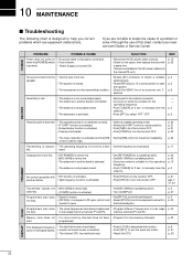
... is too low. • [RF POWER] is set too low. • [MIC GAIN] is set it through the use of this chart, contact your nearest Icom Dealer or Service Center. p. 21 pgs. 7 31, 32 Transmitted signals are • [MIC GAIN] is set mode. • Reset the CPU. start .... • Check the SEND line of an external unit, if p. 6 desired. Programmed scan does • Squelch is open p. 2 the squelch. • The transceiver is in scan edge p. 40 not start . programmed. does not change properly. • A quick set mode screen is selected. • The internal CPU has ...
... is too low. • [RF POWER] is set too low. • [MIC GAIN] is set it through the use of this chart, contact your nearest Icom Dealer or Service Center. p. 21 pgs. 7 31, 32 Transmitted signals are • [MIC GAIN] is set mode. • Reset the CPU. start .... • Check the SEND line of an external unit, if p. 6 desired. Programmed scan does • Squelch is open p. 2 the squelch. • The transceiver is in scan edge p. 40 not start . programmed. does not change properly. • A quick set mode screen is selected. • The internal CPU has ...
Instruction Manual
Page 55
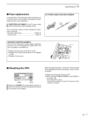
The IC-718 has 2 types of the problem, and replace the damaged fuse with a new, rated fuse. MAINTENANCE 10 s Fuse replacement If a fuse blows or the transceiver stops functioning, try to find the source of fuses installed for transceiver protection. • DC power cable fuses FGB...to turn power ON. • The internal CPU is reset. • The transceiver displays its initial VFO frequencies when resetting is applied to be displaying erroneous information, reset the CPU as shown in the IC-718 through the circuitry fuse. PA unit FGB 4 A s Resetting the CPU √...
The IC-718 has 2 types of the problem, and replace the damaged fuse with a new, rated fuse. MAINTENANCE 10 s Fuse replacement If a fuse blows or the transceiver stops functioning, try to find the source of fuses installed for transceiver protection. • DC power cable fuses FGB...to turn power ON. • The internal CPU is reset. • The transceiver displays its initial VFO frequencies when resetting is applied to be displaying erroneous information, reset the CPU as shown in the IC-718 through the circuitry fuse. PA unit FGB 4 A s Resetting the CPU √...
Instruction Manual
Page 57
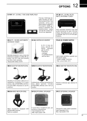
12 OPTIONS IC-PW1 HF + 50 MHz 1 KW LINER AMPLIFIER Full-duty 1 ... station operation. Includes [UP]/[DOWN] switches and a low cut function. imput power: 5 W Designed for simultaneous connection of 2 transceivers. Full break-in (QSK) operation is available. headphone jack; can connect to tune a long wire antenna for portable or mobile...8226; Output voltage: 13.8 V DC • Max. AH-4 HF + 50 MHz AUTOMATIC ANTENNA TUNER Specially designed to 2 transceivers. • Input impedance: 8 Ω • Max. HM-36 HAND MICROPHONE SP-20 EXTERNAL SPEAKER SP-21 EXTERNAL SPEAKER...
12 OPTIONS IC-PW1 HF + 50 MHz 1 KW LINER AMPLIFIER Full-duty 1 ... station operation. Includes [UP]/[DOWN] switches and a low cut function. imput power: 5 W Designed for simultaneous connection of 2 transceivers. Full break-in (QSK) operation is available. headphone jack; can connect to tune a long wire antenna for portable or mobile...8226; Output voltage: 13.8 V DC • Max. AH-4 HF + 50 MHz AUTOMATIC ANTENNA TUNER Specially designed to 2 transceivers. • Input impedance: 8 Ω • Max. HM-36 HAND MICROPHONE SP-20 EXTERNAL SPEAKER SP-21 EXTERNAL SPEAKER...
Instruction Manual
Page 58
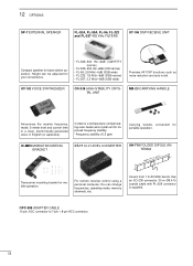
... current time in a clear, electronically-generated voice, in English (or Japanese). Covers from 1.9-30 MHz bands. IC-MB5 MOBILE MOUNTING BRACKET CT-17 CI-V LEVEL CONVERTER AH-710 FOLDED DIPOLE ANTENNA approx. 24.5 m; 80.3 ft Transceiver mounting bracket for portable operation. Has an SO-239 connector. 30 m (98.4 ft) coaxial cable with...
... current time in a clear, electronically-generated voice, in English (or Japanese). Covers from 1.9-30 MHz bands. IC-MB5 MOBILE MOUNTING BRACKET CT-17 CI-V LEVEL CONVERTER AH-710 FOLDED DIPOLE ANTENNA approx. 24.5 m; 80.3 ft Transceiver mounting bracket for portable operation. Has an SO-239 connector. 30 m (98.4 ft) coaxial cable with...
