

Instruction Manual
Page 3
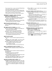
... panel 2 s Function display 5 s Rear panel 6 s Microphone (HM-36 8 3 INSTALLATION AND CONNECTIONS ......... 9 - 14 s Unpacking 9 s Selecting a location 9 s Grounding 9 s Antenna connection 9 s Required connections 10 s Advanced connections 11 s Power supply connections 12 s Liner amplifier connections 13 s External antenna tuners 14 4 FREQUENCY SETTING 15 - 19 s When first applying power 15 s Initial setting 15 s VFO description...
... panel 2 s Function display 5 s Rear panel 6 s Microphone (HM-36 8 3 INSTALLATION AND CONNECTIONS ......... 9 - 14 s Unpacking 9 s Selecting a location 9 s Grounding 9 s Antenna connection 9 s Required connections 10 s Advanced connections 11 s Power supply connections 12 s Liner amplifier connections 13 s External antenna tuners 14 4 FREQUENCY SETTING 15 - 19 s When first applying power 15 s Initial setting 15 s VFO description...
Instruction Manual
Page 5
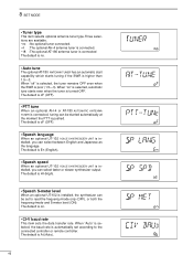
...discribed below: • [F-INP/ENT], keypad then [F-INP/ENT]. - during CW or RTTY mode, to toggle the automatic antenna tuner function ON/OFF. • An optional antenna tuner must be connected. ➥ Push for 1 sec to enter the noise blanker level setting condition. !9 QUICK TUNING STEP ... MODE SWITCHES [LSB/USB]/[CW/CW- R]/[RTTY/RTTY-R]/[AM] (p. 20) Push to manually tune the tuner. • An optional antenna tuner must be connected. • When the tuner cannot tune the antenna, the tuning circuit is bypassed automatically after 20 sec. !5 SET SWITCH [SET] ➥ Push for...
...discribed below: • [F-INP/ENT], keypad then [F-INP/ENT]. - during CW or RTTY mode, to toggle the automatic antenna tuner function ON/OFF. • An optional antenna tuner must be connected. ➥ Push for 1 sec to enter the noise blanker level setting condition. !9 QUICK TUNING STEP ... MODE SWITCHES [LSB/USB]/[CW/CW- R]/[RTTY/RTTY-R]/[AM] (p. 20) Push to manually tune the tuner. • An optional antenna tuner must be connected. • When the tuner cannot tune the antenna, the tuning circuit is bypassed automatically after 20 sec. !5 SET SWITCH [SET] ➥ Push for...
Instruction Manual
Page 8
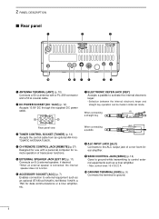
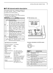
...-Icom linear amplifier. u ELECTRONIC KEYER JACK [KEY] Accepts a paddle to the ALC output jack of transceiver functions. control level: 16 V DC/2 A !0 GROUND TERMINAL [GND] (p. 9) Connects the terminal to ground. 6 When connecting (⊕) a straight key Rear panel view e TUNER CONTROL SOCKET [TUNER] (p. 14) Accepts the control cable from an optional AH-4 AUTOMATIC ANTENNA TUNER...
...-Icom linear amplifier. u ELECTRONIC KEYER JACK [KEY] Accepts a paddle to the ALC output jack of transceiver functions. control level: 16 V DC/2 A !0 GROUND TERMINAL [GND] (p. 9) Connects the terminal to ground. 6 When connecting (⊕) a straight key Rear panel view e TUNER CONTROL SOCKET [TUNER] (p. 14) Accepts the control cable from an optional AH-4 AUTOMATIC ANTENNA TUNER...
Instruction Manual
Page 11
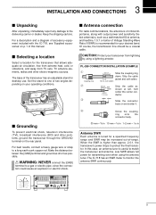
...coaxial cable. In this manual. The IC-718 has an SWR meter to a gas or electric pipe, since the connection could cause an explosion or electric shock. R WARNING: NEVER connect the [GND] terminal to monitor the antenna SWR continuously. 9 Keep the shipping cartons...sensitivity. For a description and a diagram of accessory equipment included with the IC-718, see 'Supplied accessories' on p. 1 of this case, an antenna tuner is of -range. s Antenna connection For radio communications, the antenna is useful to one of two angles depending on your transceiver from TV...
...coaxial cable. In this manual. The IC-718 has an SWR meter to a gas or electric pipe, since the connection could cause an explosion or electric shock. R WARNING: NEVER connect the [GND] terminal to monitor the antenna SWR continuously. 9 Keep the shipping cartons...sensitivity. For a description and a diagram of accessory equipment included with the IC-718, see 'Supplied accessories' on p. 1 of this case, an antenna tuner is of -range. s Antenna connection For radio communications, the antenna is useful to one of two angles depending on your transceiver from TV...
Instruction Manual
Page 12
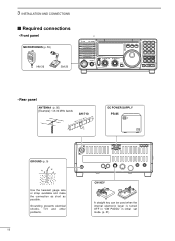
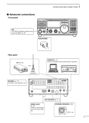
CL ˛ M V 7 8 9 SPL SCN VOX . 0 NR ANF F-INP ENT NB COMP SET P.AMP ATT TUNER ∫ CH DN UP √ • Rear panel ANTENNA (p. 56) [Example]: 1.8-30 MHz bands AH-710 approx. 24.5 m; 80.3 ft DC POWER SUPPLY PS-85 GROUND (p. 9) Use the heaviest ...gauge wire or strap available and make the connection as short as possible. 3 INSTALLATION AND CONNECTIONS s Required connections • Front panel MICROPHONES (p. 55) HM-36 SM-20 IC-718...
CL ˛ M V 7 8 9 SPL SCN VOX . 0 NR ANF F-INP ENT NB COMP SET P.AMP ATT TUNER ∫ CH DN UP √ • Rear panel ANTENNA (p. 56) [Example]: 1.8-30 MHz bands AH-710 approx. 24.5 m; 80.3 ft DC POWER SUPPLY PS-85 GROUND (p. 9) Use the heaviest ...gauge wire or strap available and make the connection as short as possible. 3 INSTALLATION AND CONNECTIONS s Required connections • Front panel MICROPHONES (p. 55) HM-36 SM-20 IC-718...
Instruction Manual
Page 13
...be input from [MIC]. (p. 33) IC-718 MODE FIL TS PWR AF RF/SQL RIT SHIFT MIC PHONES LOCK 1 2 3 V/M A=B A/B 4 5 6 MW M - EXTERNAL SPEAKER (p. 55) SP-21, etc 11 CL ∫ M V 7 8 9 SPL SCN VOX . 0 NR ANF F-INP ENT NB COMP SET P.AMP ATT TUNER ∫ CH DN UP ∫ ...HEADPHONES • Rear panel AH-4 (p. 55) with AH-2b or long wire ANTENNA (p. 13) Connects a liner amprifier, etc. [REMOTE] (p. 57) Used for connecting a non-Icom linear amplifier. ACC SOCKETS (p. 7) [SEND], [ALC] (p. ...
...be input from [MIC]. (p. 33) IC-718 MODE FIL TS PWR AF RF/SQL RIT SHIFT MIC PHONES LOCK 1 2 3 V/M A=B A/B 4 5 6 MW M - EXTERNAL SPEAKER (p. 55) SP-21, etc 11 CL ∫ M V 7 8 9 SPL SCN VOX . 0 NR ANF F-INP ENT NB COMP SET P.AMP ATT TUNER ∫ CH DN UP ∫ ...HEADPHONES • Rear panel AH-4 (p. 55) with AH-2b or long wire ANTENNA (p. 13) Connects a liner amprifier, etc. [REMOTE] (p. 57) Used for connecting a non-Icom linear amplifier. ACC SOCKETS (p. 7) [SEND], [ALC] (p. ...
Instruction Manual
Page 16
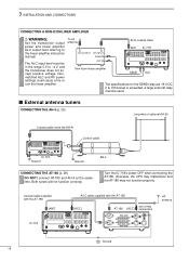
... cable supplied with the AT-180 [ACC] one of two AT-180 [ACC] connectors HF antenna IC-718 13 9 10 11 12 5678 1234 Ground 14 Both tuners will not function correctly. Turn the IC-718's power OFF when connecting the AT-180, otherwise, the CPU may malfunction and the AT-180...Coaxial cable (from the AH-4) Control cable IC-718 Ground Ground AH-4 CONNECTING THE AT-180 (p. 28) DO NOT! The ALC input level must be in the range 0 V to the linear amplifier instruction manual. 3 INSTALLATION AND CONNECTIONS CONNECTING A NON-ICOM LINER AMPLIFIER R WARNING: Set the transceiver...
... cable supplied with the AT-180 [ACC] one of two AT-180 [ACC] connectors HF antenna IC-718 13 9 10 11 12 5678 1234 Ground 14 Both tuners will not function correctly. Turn the IC-718's power OFF when connecting the AT-180, otherwise, the CPU may malfunction and the AT-180...Coaxial cable (from the AH-4) Control cable IC-718 Ground Ground AH-4 CONNECTING THE AT-180 (p. 28) DO NOT! The ALC input level must be in the range 0 V to the linear amplifier instruction manual. 3 INSTALLATION AND CONNECTIONS CONNECTING A NON-ICOM LINER AMPLIFIER R WARNING: Set the transceiver...
Instruction Manual
Page 30
...; Both turners will be "through inhibit condition. e Push [UP Y] or [Z DN] one or more times to less than 1.5:1 after tuning. NOTE: NEVER select "4" (AH-4 AUTOMATIC ANTENNA TUNER), otherwise the transceiver transmits automatically when turning the power ON. In such cases, manual tuning is selected. ing. •CW mode is selected, a side tone...
...; Both turners will be "through inhibit condition. e Push [UP Y] or [Z DN] one or more times to less than 1.5:1 after tuning. NOTE: NEVER select "4" (AH-4 AUTOMATIC ANTENNA TUNER), otherwise the transceiver transmits automatically when turning the power ON. In such cases, manual tuning is selected. ing. •CW mode is selected, a side tone...
Instruction Manual
Page 31
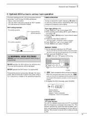
...FE-INNPT NB COMP SET P.AMP ATT TUNER CH DN UP∫ R WARNING: HIGH VOLTAGE! 5 RECEIVE AND TRANSMIT ï Optional AH-4 AUTOMATIC ANTENNA TUNER operation The AH-4 matches the IC-718 to 30 MHz. Y ∫ NEVER operate the AH-4 without an antenna wire. Note that the AH-4 cannot tune... when using a 1⁄2 λ long wire or multiple of the ham bands, the AH-4 tuner will not transmit outside...
...FE-INNPT NB COMP SET P.AMP ATT TUNER CH DN UP∫ R WARNING: HIGH VOLTAGE! 5 RECEIVE AND TRANSMIT ï Optional AH-4 AUTOMATIC ANTENNA TUNER operation The AH-4 matches the IC-718 to 30 MHz. Y ∫ NEVER operate the AH-4 without an antenna wire. Note that the AH-4 cannot tune... when using a 1⁄2 λ long wire or multiple of the ham bands, the AH-4 tuner will not transmit outside...
Instruction Manual
Page 48
... capability which starts tuning if the SWR is pushed. The default is oF (OFF). • PTT tune When an optional AH-4 or AT-180 AUTOMATIC ANTENNA TUNER is connected, tuning can select between English and Japanese as the language. When "on . • CI-V baud rate This item sets the data transfer rate...
... capability which starts tuning if the SWR is pushed. The default is oF (OFF). • PTT tune When an optional AH-4 or AT-180 AUTOMATIC ANTENNA TUNER is connected, tuning can select between English and Japanese as the language. When "on . • CI-V baud rate This item sets the data transfer rate...
Instruction Manual
Page 53
... THROUGH INHIBIT The tuner tunes the antenna even when the antenna has poor SWR (up to ground when transmitting (20 mA max). For SSB mode, the same condition is obtained at any given time. Goes to VSWR 3:1 after tuning). TUNER SENSITIVE CONDITION The tuner tunes each time ...(default) described below . Select a suitable condition according to your antenna system. ➀ Remove the top cover of the AT-180. ➁ Set the tuner switches to the desired positions according to "through inhibit," however, the tuner is higher than 1.5:1. In this case, manual tuning is ON...
... THROUGH INHIBIT The tuner tunes the antenna even when the antenna has poor SWR (up to ground when transmitting (20 mA max). For SSB mode, the same condition is obtained at any given time. Goes to VSWR 3:1 after tuning). TUNER SENSITIVE CONDITION The tuner tunes each time ...(default) described below . Select a suitable condition according to your antenna system. ➀ Remove the top cover of the AT-180. ➁ Set the tuner switches to the desired positions according to "through inhibit," however, the tuner is higher than 1.5:1. In this case, manual tuning is ON...
Instruction Manual
Page 54
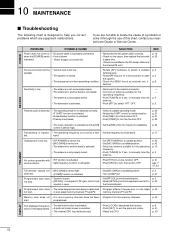
... gain control and squelch is open . in the transmitting condition. • Check the SEND line of this chart, contact your nearest Icom Dealer or Service Center. memory channels P1 and P2. start . POWER PROBLEM POSSIBLE CAUSE Power does not come on • DC ... solve it to the threshold point. distorted. • [COMP] function is activated. • Reconnect to the antenna connector. • Connect an antenna suitable for the operating frequency. • Push [TUNER] for the cause, then replace the fuse with • RIT function is activated. is activated. SOLUTION REF....
... gain control and squelch is open . in the transmitting condition. • Check the SEND line of this chart, contact your nearest Icom Dealer or Service Center. memory channels P1 and P2. start . POWER PROBLEM POSSIBLE CAUSE Power does not come on • DC ... solve it to the threshold point. distorted. • [COMP] function is activated. • Reconnect to the antenna connector. • Connect an antenna suitable for the operating frequency. • Push [TUNER] for the cause, then replace the fuse with • RIT function is activated. is activated. SOLUTION REF....
Instruction Manual
Page 57
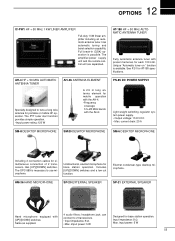
... of 2 transceivers. Same as supplied. 4 audio filters; Full break-in (QSK) operation is available. AH-4 HF + 50 MHz AUTOMATIC ANTENNA TUNER Specially designed to 2 transceivers. • Input impedance: 8 Ω • Max. Includes [UP]/[DOWN] switches and a low cut function.... Input impedance: 8 Ω Max. 12 OPTIONS IC-PW1 HF + 50 MHz 1 KW LINER AMPLIFIER Full-duty 1 kW linear amplifier including an automatic antenna tuner. AT-180 HF + 50 MHz AUTOMATIC ANTENNA TUNER Fully automatic antenna tuner with [UP]/[DOWN] switches. Has [UP]/[DOWN] switches....
... of 2 transceivers. Same as supplied. 4 audio filters; Full break-in (QSK) operation is available. AH-4 HF + 50 MHz AUTOMATIC ANTENNA TUNER Specially designed to 2 transceivers. • Input impedance: 8 Ω • Max. Includes [UP]/[DOWN] switches and a low cut function.... Input impedance: 8 Ω Max. 12 OPTIONS IC-PW1 HF + 50 MHz 1 KW LINER AMPLIFIER Full-duty 1 kW linear amplifier including an automatic antenna tuner. AT-180 HF + 50 MHz AUTOMATIC ANTENNA TUNER Fully automatic antenna tuner with [UP]/[DOWN] switches. Has [UP]/[DOWN] switches....

