

Instruction Manual
Page 3
... s Dial lock function 19 5 RECEIVE AND TRANSMIT 20 - 34 s Mode selection 20 s Squelch and RF gain 20 s Function for receive 21 s DSP function (option 23 s Filter selection 24 s Filter setting 25 s Function for transmit 26 s Split frequency operation 30 s SWR 30 s Function for CW 31 s Function for DC cable 1 r Fuse (FGB 4 A;
... s Dial lock function 19 5 RECEIVE AND TRANSMIT 20 - 34 s Mode selection 20 s Squelch and RF gain 20 s Function for receive 21 s DSP function (option 23 s Filter selection 24 s Filter setting 25 s Function for transmit 26 s Split frequency operation 30 s SWR 30 s Function for CW 31 s Function for DC cable 1 r Fuse (FGB 4 A;
Instruction Manual
Page 5
...in 1 Hz steps. ➥ While the kHz quick tuning step is selected, it enters tuning step set mode when pushed for 1 sec. @0 FILTER SWITCH [FIL] (p. 24) ➥ Push momentarily to toggle between CW and CW reverse or RTTY and RTTY reverse. The noise blanker reduces pulse-.... • An optional antenna tuner must be - during CW or RTTY mode, to toggle between the pre-programmed normal, wide and narrow IF filters for the selected operating mode. @1 MODE SWITCHES [LSB/USB]/[CW/CW- 2 PANEL DESCRIPTION • Push several functions as that generated by automobile ignition...
...in 1 Hz steps. ➥ While the kHz quick tuning step is selected, it enters tuning step set mode when pushed for 1 sec. @0 FILTER SWITCH [FIL] (p. 24) ➥ Push momentarily to toggle between CW and CW reverse or RTTY and RTTY reverse. The noise blanker reduces pulse-.... • An optional antenna tuner must be - during CW or RTTY mode, to toggle between the pre-programmed normal, wide and narrow IF filters for the selected operating mode. @1 MODE SWITCHES [LSB/USB]/[CW/CW- 2 PANEL DESCRIPTION • Push several functions as that generated by automobile ignition...
Instruction Manual
Page 6
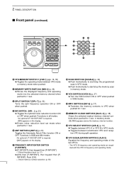
Push [CH]. - 2 PANEL DESCRIPTION s Front panel (continued) MODE FILTER TS K 1 2 3 V/M A=B A/B 4 5 6 MW M =CL M V 7 SPL .NR 8 SCN 0 ANF 9 VOX F-INP ENT NB COMP SET P.AMP ATT TUNER CH √ DN UP ∫ ˛ ˛ #3 #2 @2 1 2 3 V/M A=B A/B #1 @3 4 5 6 MW M ... frequency and operating mode into the selected memory channel when pushed for 1 sec. @6 ANF SWITCH/0 [ANF•0] (p. 23) Toggles the Automatic Notch Filter function ON or OFF. Direct memory number selection. (p. 35) @8 SCAN SWITCH/8 [SCAN•8] (p. 39) ➥ Push momentarily to start /stop...
Push [CH]. - 2 PANEL DESCRIPTION s Front panel (continued) MODE FILTER TS K 1 2 3 V/M A=B A/B 4 5 6 MW M =CL M V 7 SPL .NR 8 SCN 0 ANF 9 VOX F-INP ENT NB COMP SET P.AMP ATT TUNER CH √ DN UP ∫ ˛ ˛ #3 #2 @2 1 2 3 V/M A=B A/B #1 @3 4 5 6 MW M ... frequency and operating mode into the selected memory channel when pushed for 1 sec. @6 ANF SWITCH/0 [ANF•0] (p. 23) Toggles the Automatic Notch Filter function ON or OFF. Direct memory number selection. (p. 35) @8 SCAN SWITCH/8 [SCAN•8] (p. 39) ➥ Push momentarily to start /stop...
Instruction Manual
Page 7
... is in use. !5 FREQUENCY READOUT Shows the operating frequency. !6 REVERSE INDICATOR (p.19) Appears when the CW reverse or RTTY reverse mode is selected. !7 WIDE/NARROW FILTER INDICATORS (pgs. 24, 25) ➥" " appears when the wide IF filter is selected. ➥" " appears when the narrow IF... filter is selected. !8 PROGRAMMABLE TUNING STEP INDICATORS Appears when the programmable tuning step is installed. y DSP UNIT INDICATOR (p. 49) Appears when an optional UT-106 DSP ...
... is in use. !5 FREQUENCY READOUT Shows the operating frequency. !6 REVERSE INDICATOR (p.19) Appears when the CW reverse or RTTY reverse mode is selected. !7 WIDE/NARROW FILTER INDICATORS (pgs. 24, 25) ➥" " appears when the wide IF filter is selected. ➥" " appears when the narrow IF... filter is selected. !8 PROGRAMMABLE TUNING STEP INDICATORS Appears when the programmable tuning step is installed. y DSP UNIT INDICATOR (p. 49) Appears when an optional UT-106 DSP ...
Instruction Manual
Page 25
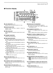
... OFF Noise components Noise reduction activated Desired signal (CW) q Push [NR] to turn the noise reduction OFF. • [NR] indicator disappears. ï ANF (Automatic Notch Filter) function When an optional UT-106 is installed (DSP appears in noise. w Push [ANF] to digital signals and then the desired signals are moving. r Push...
... OFF Noise components Noise reduction activated Desired signal (CW) q Push [NR] to turn the noise reduction OFF. • [NR] indicator disappears. ï ANF (Automatic Notch Filter) function When an optional UT-106 is installed (DSP appears in noise. w Push [ANF] to digital signals and then the desired signals are moving. r Push...
Instruction Manual
Page 26
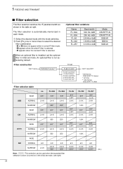
... 3.3 K 2.4 K 6 K 2.4 K 1.8 K* 6 K 2.4 K 3.3 K* ( Hz ) 24 An optional filter is automatically memorized in the table at right. Normal ** OPTION *** AM; Normal, SSB/CW/RTTY; Wide • Filter selection table no FL-52A FL-53A WIDE 6 K* 6 K* 6 K* SSB NORMAL 2.4 K 2.4 K 2.4 K NARROW 500* 250* WIDE 6 K* 6 K* 6 K* CW NORMAL 2.4 K 2.4 K 2.4 K NARROW 500 250 WIDE 6 K* ... K 2.4 K 500* 2.4 K 250* Note: *This selection can be used when the expanded filter selection function is installed, set the optional filter in the initial set mode. q Select the...
... 3.3 K 2.4 K 6 K 2.4 K 1.8 K* 6 K 2.4 K 3.3 K* ( Hz ) 24 An optional filter is automatically memorized in the table at right. Normal ** OPTION *** AM; Normal, SSB/CW/RTTY; Wide • Filter selection table no FL-52A FL-53A WIDE 6 K* 6 K* 6 K* SSB NORMAL 2.4 K 2.4 K 2.4 K NARROW 500* 250* WIDE 6 K* 6 K* 6 K* CW NORMAL 2.4 K 2.4 K 2.4 K NARROW 500 250 WIDE 6 K* ... K 2.4 K 500* 2.4 K 250* Note: *This selection can be used when the expanded filter selection function is installed, set the optional filter in the initial set mode. q Select the...
Instruction Manual
Page 27
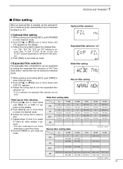
.... • Wide filter setting q While pushing and holding [SET], push [POWER] to select IF filters for 455 kHz IF filter selection. Optional filters are stored depending on ' is installed, set... - - FL-222 222 (1.8 K) 222 (1.8 K) FL-257 257(3.3 k) THU (6 K) 257(3.3 k) THU (6 K) 257(3.3 k) THU (6 K) - - - : default FL-257 - - - - - - sired. •The filter combinations are not selected by setting the expanded filter selection to select a filter. NOR (2.4 K) NOR (2.4 K) NOR (2.4 K) NOR (2.4 K) NOR (2.4 K) NOR (2.4 K) AM 52A (500) 53A...
.... • Wide filter setting q While pushing and holding [SET], push [POWER] to select IF filters for 455 kHz IF filter selection. Optional filters are stored depending on ' is installed, set... - - FL-222 222 (1.8 K) 222 (1.8 K) FL-257 257(3.3 k) THU (6 K) 257(3.3 k) THU (6 K) 257(3.3 k) THU (6 K) - - - : default FL-257 - - - - - - sired. •The filter combinations are not selected by setting the expanded filter selection to select a filter. NOR (2.4 K) NOR (2.4 K) NOR (2.4 K) NOR (2.4 K) NOR (2.4 K) NOR (2.4 K) AM 52A (500) 53A...
Instruction Manual
Page 31
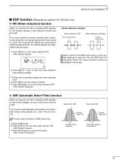
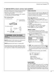
AH-4 setting example: For mobile operation Optional AH-2b antenna element For outdoor operation Long wire AH-4 IC-718 MODE FILTER TS PWR AF SQL RIT SHIFT MIC PHONES LOCK ˛ V/M1 A=B2 A/B3 MW4 M=C5L M V6 SP7L SCN8 VOX9 .NR ANF0 FE-INNPT ...is complete. • When the connected wire cannot be damaged. 5 RECEIVE AND TRANSMIT ï Optional AH-4 AUTOMATIC ANTENNA TUNER operation The AH-4 matches the IC-718 to a long wire antenna more than 1%). tion and antenna connection details. NEVER touch the antenna element while tuning or transmitting. • Tuner type setting ...
AH-4 setting example: For mobile operation Optional AH-2b antenna element For outdoor operation Long wire AH-4 IC-718 MODE FILTER TS PWR AF SQL RIT SHIFT MIC PHONES LOCK ˛ V/M1 A=B2 A/B3 MW4 M=C5L M V6 SP7L SCN8 VOX9 .NR ANF0 FE-INNPT ...is complete. • When the connected wire cannot be damaged. 5 RECEIVE AND TRANSMIT ï Optional AH-4 AUTOMATIC ANTENNA TUNER operation The AH-4 matches the IC-718 to a long wire antenna more than 1%). tion and antenna connection details. NEVER touch the antenna element while tuning or transmitting. • Tuner type setting ...
Instruction Manual
Page 49
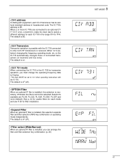
... mode and see P. 50 for filter installation. • Expand Filter When an optional IF filter is on operating mode independently. • CI-V address To distinguish equipment, each IC-718 in hexadecimal code. When 2 or more IC-718s are FL-96, FL-222, FL-52A, FL-53A, FL-257 ...(off ). • OPTION Filter When an optional IF filer is installed, this selection expands filter and filter selection (W/N) key combination on . • CI-V 731 mode When connecting the IC-718 to the IC-735 for each CI-V transceiver has its own Icom standard address in the range ...
... mode and see P. 50 for filter installation. • Expand Filter When an optional IF filter is on operating mode independently. • CI-V address To distinguish equipment, each IC-718 in hexadecimal code. When 2 or more IC-718s are FL-96, FL-222, FL-52A, FL-53A, FL-257 ...(off ). • OPTION Filter When an optional IF filer is installed, this selection expands filter and filter selection (W/N) key combination on . • CI-V 731 mode When connecting the IC-718 to the IC-735 for each CI-V transceiver has its own Icom standard address in the range ...
Instruction Manual
Page 52
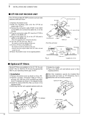
... Install the desired 455 KHz filter as shown on the MAIN unit. Optional IF filter J 1 W 5 J 701 J 4101 MAIN unit Tr-clamper Solder 4 leads Tr-clamper 50 After filter installation, specify the installed filter using initial set mode. (p. 47) Otherwise, the installed filter will not function ... cable J 2602 Rear panel UT-106 J 2603 Main unit * Supplied with an adhesive strip, etc. You can install 1 filter for the IC-718. t Plug the flat cable into J1 on the MAIN unit. • No need to fix with UT-106 s Optional IF filters...
... Install the desired 455 KHz filter as shown on the MAIN unit. Optional IF filter J 1 W 5 J 701 J 4101 MAIN unit Tr-clamper Solder 4 leads Tr-clamper 50 After filter installation, specify the installed filter using initial set mode. (p. 47) Otherwise, the installed filter will not function ... cable J 2602 Rear panel UT-106 J 2603 Main unit * Supplied with an adhesive strip, etc. You can install 1 filter for the IC-718. t Plug the flat cable into J1 on the MAIN unit. • No need to fix with UT-106 s Optional IF filters...
Instruction Manual
Page 57
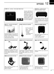
...for base station operation. AT-180 HF + 50 MHz AUTOMATIC ANTENNA TUNER Fully automatic antenna tuner with [UP]/[DOWN] switches. Same as supplied. 4 audio filters; Input impedance: 8 Ω Max. The amplifier/power supply unit and the remote control unit are separated. Electret condenser-type desktop microphone. See P. 51... for AT-180 specifications. input power: 5 W 55 12 OPTIONS IC-PW1 HF + 50 MHz 1 KW LINER AMPLIFIER Full-duty 1 kW linear amplifier including an automatic antenna tuner.
...for base station operation. AT-180 HF + 50 MHz AUTOMATIC ANTENNA TUNER Fully automatic antenna tuner with [UP]/[DOWN] switches. Same as supplied. 4 audio filters; Input impedance: 8 Ω Max. The amplifier/power supply unit and the remote control unit are separated. Electret condenser-type desktop microphone. See P. 51... for AT-180 specifications. input power: 5 W 55 12 OPTIONS IC-PW1 HF + 50 MHz 1 KW LINER AMPLIFIER Full-duty 1 kW linear amplifier including an automatic antenna tuner.
Instruction Manual
Page 58
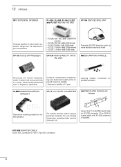
12 OPTIONS SP-7 EXTERNAL SPEAKER FL-52A, FL-53A, FL-96, FL-222 and FL-257 455 KHz FILTERS UT-106 DSP RECEIVE UNIT Compact speaker for portable operation. For remote receiver control using a personal computer. You can be adjusted for mobile... crystal unit for improved frequency stability. • Frequency stability: ±0.5 ppm Carrying handle, convenient for base station operation. Covers from 1.9-30 MHz bands. IC-MB5 MOBILE MOUNTING BRACKET CT-17 CI-V LEVEL CONVERTER AH-710 FOLDED DIPOLE ANTENNA approx. 24.5 m; 80.3 ft Transceiver mounting bracket for your convenience. ...
12 OPTIONS SP-7 EXTERNAL SPEAKER FL-52A, FL-53A, FL-96, FL-222 and FL-257 455 KHz FILTERS UT-106 DSP RECEIVE UNIT Compact speaker for portable operation. For remote receiver control using a personal computer. You can be adjusted for mobile... crystal unit for improved frequency stability. • Frequency stability: ±0.5 ppm Carrying handle, convenient for base station operation. Covers from 1.9-30 MHz bands. IC-MB5 MOBILE MOUNTING BRACKET CT-17 CI-V LEVEL CONVERTER AH-710 FOLDED DIPOLE ANTENNA approx. 24.5 m; 80.3 ft Transceiver mounting bracket for your convenience. ...
Instruction Manual
Page 61
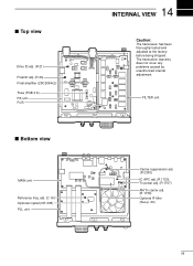
s Top view Drive ID adj. (R 21) Final ID adj. (R 24) Final amplifier (2SC2094x2) Fuse (FGB 4 A) PA unit R 25 s Bottom view MAIN unit Reference freq. FILTER unit Carrier suppression adj. (R 2303) IC APC adj. (R 1720) Tx power adj. (R 1707) AM Tx carrier adj. (R 1730) Optional IF filter (See p. 24) 59 The transceiver warranty does not cover any problems caused by unauthorized internal adjustment. adj. (C 16) Optional crystal (CR-338) PLL unit 14 INTERNAL VIEW Caution: The transceiver has been thoroughly tested and adjusted at the factory before being shipped.
s Top view Drive ID adj. (R 21) Final ID adj. (R 24) Final amplifier (2SC2094x2) Fuse (FGB 4 A) PA unit R 25 s Bottom view MAIN unit Reference freq. FILTER unit Carrier suppression adj. (R 2303) IC APC adj. (R 1720) Tx power adj. (R 1707) AM Tx carrier adj. (R 1730) Optional IF filter (See p. 24) 59 The transceiver warranty does not cover any problems caused by unauthorized internal adjustment. adj. (C 16) Optional crystal (CR-338) PLL unit 14 INTERNAL VIEW Caution: The transceiver has been thoroughly tested and adjusted at the factory before being shipped.

