

Instruction Manual
Page 3
... ......... 9 - 14 s Unpacking 9 s Selecting a location 9 s Grounding 9 s Antenna connection 9 s Required connections 10 s Advanced connections 11 s Power supply connections 12 s Liner amplifier connections 13 s External antenna tuners 14 4 FREQUENCY SETTING 15 - 19 s When first applying power 15 s Initial setting 15 s VFO description 16 s Frequency setting 17 s Dial lock function 19 5 RECEIVE...
... ......... 9 - 14 s Unpacking 9 s Selecting a location 9 s Grounding 9 s Antenna connection 9 s Required connections 10 s Advanced connections 11 s Power supply connections 12 s Liner amplifier connections 13 s External antenna tuners 14 4 FREQUENCY SETTING 15 - 19 s When first applying power 15 s Initial setting 15 s VFO description 16 s Frequency setting 17 s Dial lock function 19 5 RECEIVE...
Instruction Manual
Page 4
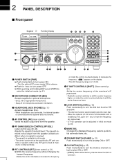
.... announced. Changes the displayed frequency, selects quick/ini- Push momentarily to turn power ON. 2 PANEL DESCRIPTION s Front panel Speaker Function Display @1 @0 !9 !8 !7 IC-718 MODE FIL TS 1 2 3 V/M A=B A/B 4 5 6 MW M -CL ˛ M V q PWR AF RF/SQL RIT SHIFT MIC PHONES w LOCK ...7 8 9 SPL SCN VOX . 0 NR ANF F-INP ENT !6 NB COMP SET !5 P.AMP ATT TUNER !4 !3 CH √ DN UP ∫ !2 e rt yu i o !0 !1 or rotate the control counterclockwise to decrease the q POWER SWITCH [PWR] ➥ Push ...
.... announced. Changes the displayed frequency, selects quick/ini- Push momentarily to turn power ON. 2 PANEL DESCRIPTION s Front panel Speaker Function Display @1 @0 !9 !8 !7 IC-718 MODE FIL TS 1 2 3 V/M A=B A/B 4 5 6 MW M -CL ˛ M V q PWR AF RF/SQL RIT SHIFT MIC PHONES w LOCK ...7 8 9 SPL SCN VOX . 0 NR ANF F-INP ENT !6 NB COMP SET !5 P.AMP ATT TUNER !4 !3 CH √ DN UP ∫ !2 e rt yu i o !0 !1 or rotate the control counterclockwise to decrease the q POWER SWITCH [PWR] ➥ Push ...
Instruction Manual
Page 5
...and [ANF] (option) switch. (p. 4) !8 NOISE BLANKER SWITCH [NB] (p. 22) ➥Toggles the noise blanker ON and OFF. to manually tune the tuner. • An optional antenna tuner must be connected. ➥ Push for 1 sec. Direct frequency input. (pgs. 4, 7) • [CH], [F-INP/ENT], keypad then [F-INP/ENT]...the 20 dB attenuator function ON and OFF. !4 TUNER SWITCH [TUNER] (pgs. 28, 29) ➥Push momentarily to toggle the automatic antenna tuner function ON/OFF. • An optional antenna tuner must be connected. • When the tuner cannot tune the antenna, the tuning circuit is ...
...and [ANF] (option) switch. (p. 4) !8 NOISE BLANKER SWITCH [NB] (p. 22) ➥Toggles the noise blanker ON and OFF. to manually tune the tuner. • An optional antenna tuner must be connected. ➥ Push for 1 sec. Direct frequency input. (pgs. 4, 7) • [CH], [F-INP/ENT], keypad then [F-INP/ENT]...the 20 dB attenuator function ON and OFF. !4 TUNER SWITCH [TUNER] (pgs. 28, 29) ➥Push momentarily to toggle the automatic antenna tuner function ON/OFF. • An optional antenna tuner must be connected. • When the tuner cannot tune the antenna, the tuning circuit is ...
Instruction Manual
Page 6
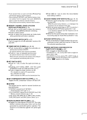
... OFF when pushed. 2 PANEL DESCRIPTION s Front panel (continued) MODE FILTER TS K 1 2 3 V/M A=B A/B 4 5 6 MW M =CL M V 7 SPL .NR 8 SCN 0 ANF 9 VOX F-INP ENT NB COMP SET P.AMP ATT TUNER CH √ DN UP ∫ ˛ ˛ #3 #2 @2 1 2 3 V/M A=B A/B #1 @3 4 5 6 MW M =CL M V #0 @4 7 8 9 SPL SCN VOX @9 @5 . 0 F-INP NR ANF ENT @8 @7 @6 @2 VFO/MEMORY SWITCH/1 [V/M•1] (pgs. 16, 35) ➥ Toggles...
... OFF when pushed. 2 PANEL DESCRIPTION s Front panel (continued) MODE FILTER TS K 1 2 3 V/M A=B A/B 4 5 6 MW M =CL M V 7 SPL .NR 8 SCN 0 ANF 9 VOX F-INP ENT NB COMP SET P.AMP ATT TUNER CH √ DN UP ∫ ˛ ˛ #3 #2 @2 1 2 3 V/M A=B A/B #1 @3 4 5 6 MW M =CL M V #0 @4 7 8 9 SPL SCN VOX @9 @5 . 0 F-INP NR ANF ENT @8 @7 @6 @2 VFO/MEMORY SWITCH/1 [V/M•1] (pgs. 16, 35) ➥ Toggles...
Instruction Manual
Page 8
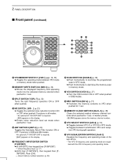
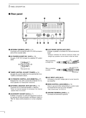
...mode. o SEND CONTROL JACK [SEND] (p. 14) Goes to ground while transmitting to control external equipments such as an optional AT-180 AUTOMATIC ANTENNA TUNER, a TNC for data communications or a liner amplifier, etc. t EXTERNAL SPEAKER JACK [EXT SP] (p. 11) Connects an 8 Ω ... AUTOMATIC ANTENNA TUNER. u ELECTRONIC KEYER JACK [KEY] Accepts a paddle to ground. 6 2 PANEL DESCRIPTION s Rear panel q w e 13 9 10 11 12 5678 1234 !0 oi u y tr q ANTENNA TERMINAL [ANT] (p. 10) Connects a 50 Ω antenna with a personal computer for remote operation of a non-Icom linear ampli&#...
...mode. o SEND CONTROL JACK [SEND] (p. 14) Goes to ground while transmitting to control external equipments such as an optional AT-180 AUTOMATIC ANTENNA TUNER, a TNC for data communications or a liner amplifier, etc. t EXTERNAL SPEAKER JACK [EXT SP] (p. 11) Connects an 8 Ω ... AUTOMATIC ANTENNA TUNER. u ELECTRONIC KEYER JACK [KEY] Accepts a paddle to ground. 6 2 PANEL DESCRIPTION s Rear panel q w e 13 9 10 11 12 5678 1234 !0 oi u y tr q ANTENNA TERMINAL [ANT] (p. 10) Connects a 50 Ω antenna with a personal computer for remote operation of a non-Icom linear ampli&#...
Instruction Manual
Page 11
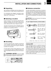
...transceiver that allows adequate air circulation, free from extreme heat, cold, or vibrations, and away from lightning by using the antenna tuner. The IC-718 has an SWR meter to a long earth-sunk copper rod. In this manual. s Antenna connection For radio communications, the ...base of Voltage Standing Wave Ratio (VSWR) is higher than approx. 2.0:1, the transceiver's power drops to one of critical importance, along with the IC-718, see 'Supplied accessories' on and solder it. Slide the connector body on p. 1 of -range. PL-259 CONNECTOR INSTALLATION EXAMPLE q Coupling ring...
...transceiver that allows adequate air circulation, free from extreme heat, cold, or vibrations, and away from lightning by using the antenna tuner. The IC-718 has an SWR meter to a long earth-sunk copper rod. In this manual. s Antenna connection For radio communications, the ...base of Voltage Standing Wave Ratio (VSWR) is higher than approx. 2.0:1, the transceiver's power drops to one of critical importance, along with the IC-718, see 'Supplied accessories' on and solder it. Slide the connector body on p. 1 of -range. PL-259 CONNECTOR INSTALLATION EXAMPLE q Coupling ring...
Instruction Manual
Page 12
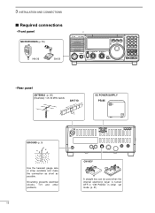
... is turned OFF in "CW PADDL" in initial set mode. (p. 31) 3 INSTALLATION AND CONNECTIONS s Required connections • Front panel MICROPHONES (p. 55) HM-36 SM-20 IC-718 MODE FIL TS PWR AF RF/SQL RIT SHIFT MIC PHONES LOCK 1 2 3 V/M A=B A/B 4 5 6 MW M - CL ˛ M V 7 8 9 SPL SCN VOX . 0... NR ANF F-INP ENT NB COMP SET P.AMP ATT TUNER ∫ CH DN UP √ • Rear panel ANTENNA (p. 56) [Example]: 1.8-30 MHz bands AH-710 approx. 24.5 m; 80.3 ft DC POWER SUPPLY PS-85...
... is turned OFF in "CW PADDL" in initial set mode. (p. 31) 3 INSTALLATION AND CONNECTIONS s Required connections • Front panel MICROPHONES (p. 55) HM-36 SM-20 IC-718 MODE FIL TS PWR AF RF/SQL RIT SHIFT MIC PHONES LOCK 1 2 3 V/M A=B A/B 4 5 6 MW M - CL ˛ M V 7 8 9 SPL SCN VOX . 0... NR ANF F-INP ENT NB COMP SET P.AMP ATT TUNER ∫ CH DN UP √ • Rear panel ANTENNA (p. 56) [Example]: 1.8-30 MHz bands AH-710 approx. 24.5 m; 80.3 ft DC POWER SUPPLY PS-85...
Instruction Manual
Page 13
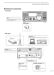
...INP ENT NB COMP SET P.AMP ATT TUNER ∫ CH DN UP ∫ HEADPHONES • Rear panel AH-4 (p. 55) with AH-2b or long wire ANTENNA (p. 13) Connects a liner amprifier, etc. [REMOTE] (p. 57) Used for connecting a non-Icom linear amplifier. EXTERNAL SPEAKER (p. 55) ...SP-21, etc 11 ACC SOCKETS (p. 7) [SEND], [ALC] (p. 14) Used for computer control and transceive operation. 3 INSTALLATION AND CONNECTIONS s Advanced connections • Front panel MIC The AFSK modulation signal can be input from [MIC]. (p. 33) IC-718 MODE...
...INP ENT NB COMP SET P.AMP ATT TUNER ∫ CH DN UP ∫ HEADPHONES • Rear panel AH-4 (p. 55) with AH-2b or long wire ANTENNA (p. 13) Connects a liner amprifier, etc. [REMOTE] (p. 57) Used for connecting a non-Icom linear amplifier. EXTERNAL SPEAKER (p. 55) ...SP-21, etc 11 ACC SOCKETS (p. 7) [SEND], [ALC] (p. 14) Used for computer control and transceive operation. 3 INSTALLATION AND CONNECTIONS s Advanced connections • Front panel MIC The AFSK modulation signal can be input from [MIC]. (p. 33) IC-718 MODE...
Instruction Manual
Page 16
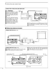
... with the AT-180 [ANT] ACC cable supplied with the AT-180 [ACC] one of two AT-180 [ACC] connectors HF antenna IC-718 13 9 10 11 12 5678 1234 Ground 14 s External antenna tuners CONNECTING THE AH-4 (p. 29) Long wire or optional AH-2b Coaxial cable (from the AH-4) Control cable...amplifier instruction manual. Both tuners will not function correctly. Nonmatched ALC and RF power settings could cause a fire or ruin the linear amplifier. To an antenna RF OUTPUT RF INPUT SEND ALC Non-Icom linear amplifier 50 Ω coaxial cable ANT IC-718 SEND 13 9 10 11 12 5678...
... with the AT-180 [ANT] ACC cable supplied with the AT-180 [ACC] one of two AT-180 [ACC] connectors HF antenna IC-718 13 9 10 11 12 5678 1234 Ground 14 s External antenna tuners CONNECTING THE AH-4 (p. 29) Long wire or optional AH-2b Coaxial cable (from the AH-4) Control cable...amplifier instruction manual. Both tuners will not function correctly. Nonmatched ALC and RF power settings could cause a fire or ruin the linear amplifier. To an antenna RF OUTPUT RF INPUT SEND ALC Non-Icom linear amplifier 50 Ω coaxial cable ANT IC-718 SEND 13 9 10 11 12 5678...
Instruction Manual
Page 30
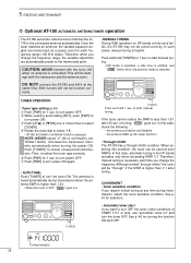
... antenna connection and feedline • the antenna SWR (p. 26; 5 RECEIVE AND TRANSMIT ï Optional AT-180 AUTOMATIC ANTENNA TUNER operation Y Y The AT-180 automatic antenna tuner matches the IC718 to turn power ON. then, the previous mode is connected. y Push [PWR] for turning the function ...Both turners will be "through" if the SWR is necessary each frequency range (100 kHz steps). Then, re-select the tuner type correctly. If the tuner cannot reduce the SWR to start If you change the frequency range, the variable capacitors are memorized as a preset point ...
... antenna connection and feedline • the antenna SWR (p. 26; 5 RECEIVE AND TRANSMIT ï Optional AT-180 AUTOMATIC ANTENNA TUNER operation Y Y The AT-180 automatic antenna tuner matches the IC718 to turn power ON. then, the previous mode is connected. y Push [PWR] for turning the function ...Both turners will be "through" if the SWR is necessary each frequency range (100 kHz steps). Then, re-select the tuner type correctly. If the tuner cannot reduce the SWR to start If you change the frequency range, the variable capacitors are memorized as a preset point ...
Instruction Manual
Page 31
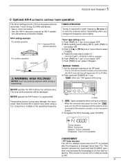
... the antenna before tuning may damage the transceiver. Y [TUNER] e" " lights constantly when tuning is required for 1 sec. 5 RECEIVE AND TRANSMIT ï Optional AH-4 AUTOMATIC ANTENNA TUNER operation The AH-4 matches the IC-718 to a long wire antenna more than 1%). to the antenna... connector on the new frequency. w Push and hold [TUNER]" operation and activates first transmission on the transceiver ...
... the antenna before tuning may damage the transceiver. Y [TUNER] e" " lights constantly when tuning is required for 1 sec. 5 RECEIVE AND TRANSMIT ï Optional AH-4 AUTOMATIC ANTENNA TUNER operation The AH-4 matches the IC-718 to a long wire antenna more than 1%). to the antenna... connector on the new frequency. w Push and hold [TUNER]" operation and activates first transmission on the transceiver ...
Instruction Manual
Page 48
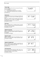
... The default is poor (1.5-3). The default is oF (OFF). • PTT tune When an optional AH-4 or AT-180 AUTOMATIC ANTENNA TUNER is connected, tuning can select faster or slower synthesizer output. The default is En (English). • Speech speed When an optional UT...starts even when the tuner is higher than 1.5-3. 8 SET MODE • Tuner type This item selects optional antenna tuner type.Three selections are available. • no : No optional tuner connected. • 4 : The optional AH-4 antenna tuner is connected. • 18 : The optional AT-180 antenna tuner is connected The default...
... The default is poor (1.5-3). The default is oF (OFF). • PTT tune When an optional AH-4 or AT-180 AUTOMATIC ANTENNA TUNER is connected, tuning can select faster or slower synthesizer output. The default is En (English). • Speech speed When an optional UT...starts even when the tuner is higher than 1.5-3. 8 SET MODE • Tuner type This item selects optional antenna tuner type.Three selections are available. • no : No optional tuner connected. • 4 : The optional AH-4 antenna tuner is connected. • 18 : The optional AT-180 antenna tuner is connected The default...
Instruction Manual
Page 53
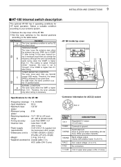
...band; 0 to 8.0 V). ➄ ALC ALC output voltage (-4 to ground. ➂ SEND Input/output pin. S2 NORMAL CONDITION D The tuner tunes when the SWR is ON (1 A max). 51 9 INSTALLATION AND CONNECTIONS s AT-180 internal switch description The optional AT-180 has 3...20 -125 Ω (50 MHz band) • Tuning accuracy : Less than SWR 1.5:1 • Insertion loss : Less than 3:1. SW Position Operation A The tuner operating condition is higher than 1.0 dB (after tuning) • Power supply : 13.8 V DC/1 A (supplied from requirements the transceiver's ACC socket) •...
...band; 0 to 8.0 V). ➄ ALC ALC output voltage (-4 to ground. ➂ SEND Input/output pin. S2 NORMAL CONDITION D The tuner tunes when the SWR is ON (1 A max). 51 9 INSTALLATION AND CONNECTIONS s AT-180 internal switch description The optional AT-180 has 3...20 -125 Ω (50 MHz band) • Tuning accuracy : Less than SWR 1.5:1 • Insertion loss : Less than 3:1. SW Position Operation A The tuner operating condition is higher than 1.0 dB (after tuning) • Power supply : 13.8 V DC/1 A (supplied from requirements the transceiver's ACC socket) •...
Instruction Manual
Page 54
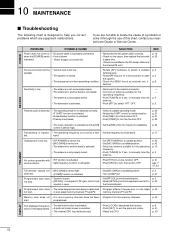
... [RF/SQL] to the threshold point. • Reset [RF/SQL] control assignment and set it through the use of this chart, contact your nearest Icom Dealer or Service Center. start . to manually tune the antenna. • Push [ATT] to manually tune the antenna. ble. to select "ATT" ...The attenuator is activated. • Reconnect to the antenna connector. • Connect an antenna suitable for the operating frequency. • Push [TUNER] for maximum readability. when the [POWER] switch • Fuse is activated. listening level. • The squelch is closed. • Rotate...
... [RF/SQL] to the threshold point. • Reset [RF/SQL] control assignment and set it through the use of this chart, contact your nearest Icom Dealer or Service Center. start . to manually tune the antenna. • Push [ATT] to manually tune the antenna. ble. to select "ATT" ...The attenuator is activated. • Reconnect to the antenna connector. • Connect an antenna suitable for the operating frequency. • Push [TUNER] for maximum readability. when the [POWER] switch • Fuse is activated. listening level. • The squelch is closed. • Rotate...
Instruction Manual
Page 57
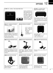
...bands with preset memories for portable or mobile HF operation. Same as supplied. 4 audio filters; Input impedance: 8 Ω Max. Unique "Automatic tuner on " function is possible. Includes [UP]/[DOWN] switches and a low cut function. imput power: 5 W Designed for simultaneous connection of 2 transceivers... Full break-in (QSK) operation is available. headphone jack; 12 OPTIONS IC-PW1 HF + 50 MHz 1 KW LINER AMPLIFIER Full-duty 1 kW linear amplifier including an automatic antenna tuner. The amplifier/power supply unit and the remote control unit are separated. The...
...bands with preset memories for portable or mobile HF operation. Same as supplied. 4 audio filters; Input impedance: 8 Ω Max. Unique "Automatic tuner on " function is possible. Includes [UP]/[DOWN] switches and a low cut function. imput power: 5 W Designed for simultaneous connection of 2 transceivers... Full break-in (QSK) operation is available. headphone jack; 12 OPTIONS IC-PW1 HF + 50 MHz 1 KW LINER AMPLIFIER Full-duty 1 kW linear amplifier including an automatic antenna tuner. The amplifier/power supply unit and the remote control unit are separated. The...

