
Instruction Manual
Page 2
... AC to operate the transceiver. During mobile operation, DO NOT operate the transceiver without running the vehicle's engine. Versions of the IC-718 which display the "CE" symbol on the rear panel of the transceiver. This may result in direct sunlight. AVOID placing the ... injury, fire or electric shock. This will obstruct heat dissipation. IMPORTANT READ THIS INSTRUCTION MANUAL CAREFULLY before starting the vehicle. Use Icom microphones only (supplied or optional). AVOID using or placing the transceiver in an electric shock. If a linear amplifier is connected, set the...
... AC to operate the transceiver. During mobile operation, DO NOT operate the transceiver without running the vehicle's engine. Versions of the IC-718 which display the "CE" symbol on the rear panel of the transceiver. This may result in direct sunlight. AVOID placing the ... injury, fire or electric shock. This will obstruct heat dissipation. IMPORTANT READ THIS INSTRUCTION MANUAL CAREFULLY before starting the vehicle. Use Icom microphones only (supplied or optional). AVOID using or placing the transceiver in an electric shock. If a linear amplifier is connected, set the...

Instruction Manual
Page 3
q DC power cable 1 w Hand microphone (HM-36 1 e Fuse (FGB 20 A; internal use 1 er 1 for RTTY 33 6 MEMORY OPERATION 35 - 38 s Memory channels 35 s...Qty. 1 TABLE OF CONTENTS IMPORTANT i EXPLICIT DEFINITIONS i PRECAUTIONS i 1 TABLE OF CONTENTS 1 SUPPLIED ACCESSORIES 1 2 PANEL DESCRIPTION 2 - 8 s Front panel 2 s Function display 5 s Rear panel 6 s Microphone (HM-36 8 3 INSTALLATION AND CONNECTIONS ......... 9 - 14 s Unpacking 9 s Selecting a location 9 s Grounding 9 s Antenna connection 9 s Required connections 10 s Advanced connections 11 s Power supply connections 12 ...
q DC power cable 1 w Hand microphone (HM-36 1 e Fuse (FGB 20 A; internal use 1 er 1 for RTTY 33 6 MEMORY OPERATION 35 - 38 s Memory channels 35 s...Qty. 1 TABLE OF CONTENTS IMPORTANT i EXPLICIT DEFINITIONS i PRECAUTIONS i 1 TABLE OF CONTENTS 1 SUPPLIED ACCESSORIES 1 2 PANEL DESCRIPTION 2 - 8 s Front panel 2 s Function display 5 s Rear panel 6 s Microphone (HM-36 8 3 INSTALLATION AND CONNECTIONS ......... 9 - 14 s Unpacking 9 s Selecting a location 9 s Grounding 9 s Antenna connection 9 s Required connections 10 s Advanced connections 11 s Power supply connections 12 ...
Instruction Manual
Page 4
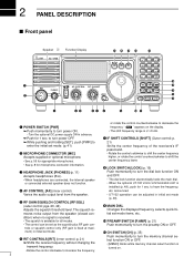
... for 1 sec. announced. The squelch re- dition) when no signal is received. • The squelch is available for microphone connector information. Varies the audio output level from the speaker (closed con- mum) in advance. ➥ Push for 1 ... headphones (8 Ω). • When headphones are connected, the internal speaker Push momentarily to turn power ON. 2 PANEL DESCRIPTION s Front panel Speaker Function Display @1 @0 !9 !8 !7 IC-718 MODE FIL TS 1 2 3 V/M A=B A/B 4 5 6 MW M -CL ˛ M V q PWR AF RF/SQL RIT SHIFT MIC PHONES w LOCK 7 8 9 SPL...
... for 1 sec. announced. The squelch re- dition) when no signal is received. • The squelch is available for microphone connector information. Varies the audio output level from the speaker (closed con- mum) in advance. ➥ Push for 1 ... headphones (8 Ω). • When headphones are connected, the internal speaker Push momentarily to turn power ON. 2 PANEL DESCRIPTION s Front panel Speaker Function Display @1 @0 !9 !8 !7 IC-718 MODE FIL TS 1 2 3 V/M A=B A/B 4 5 6 MW M -CL ˛ M V q PWR AF RF/SQL RIT SHIFT MIC PHONES w LOCK 7 8 9 SPL...
Instruction Manual
Page 10
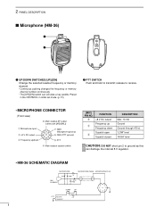
...the frequency or memory channel number continuously. • The [UP]/[DN] switch can damage the internal 8 V regulator. • HM-36 SCHEMATIC DIAGRAM MICROPHONE MICROPHONE CABLE MICROPHONE PLUG MIC ELEMENT + 10µ 2k 4700p + 0.33µ 4700p DOWN UP qu wiy ert PTT RECEIVE 470 TRANSMIT 8 w FUNCTION +8 V ...(p. 31) w PTT SWITCH Push and hold to ground as this can simulate a key paddle. release to receive. • MICROPHONE CONNECTOR (Front view) q Microphone input w +8 V DC output e Frequency up e Frequency down i Main readout AF output (varies with [AF]/[BAL]) u GND...
...the frequency or memory channel number continuously. • The [UP]/[DN] switch can damage the internal 8 V regulator. • HM-36 SCHEMATIC DIAGRAM MICROPHONE MICROPHONE CABLE MICROPHONE PLUG MIC ELEMENT + 10µ 2k 4700p + 0.33µ 4700p DOWN UP qu wiy ert PTT RECEIVE 470 TRANSMIT 8 w FUNCTION +8 V ...(p. 31) w PTT SWITCH Push and hold to ground as this can simulate a key paddle. release to receive. • MICROPHONE CONNECTOR (Front view) q Microphone input w +8 V DC output e Frequency up e Frequency down i Main readout AF output (varies with [AF]/[BAL]) u GND...
Instruction Manual
Page 12
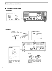
... the internal electronic keyer is turned OFF in "CW PADDL" in initial set mode. (p. 31) 3 INSTALLATION AND CONNECTIONS s Required connections • Front panel MICROPHONES (p. 55) HM-36 SM-20 IC-718 MODE FIL TS PWR AF RF/SQL RIT SHIFT MIC PHONES LOCK 1 2 3 V/M A=B A/B 4 5 6 MW M - CL ˛ M V 7 8 9 SPL SCN VOX . 0 NR ANF F-INP ENT...
... the internal electronic keyer is turned OFF in "CW PADDL" in initial set mode. (p. 31) 3 INSTALLATION AND CONNECTIONS s Required connections • Front panel MICROPHONES (p. 55) HM-36 SM-20 IC-718 MODE FIL TS PWR AF RF/SQL RIT SHIFT MIC PHONES LOCK 1 2 3 V/M A=B A/B 4 5 6 MW M - CL ˛ M V 7 8 9 SPL SCN VOX . 0 NR ANF F-INP ENT...
Instruction Manual
Page 28
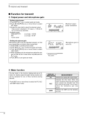
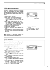
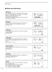
... one or more times to select the PO, ALC and SWR meter mode. q Select SSB or another phone mode. r When speaking into the microphone adjust the mic gain so that your signal does not distort when transmitted. t Push [SET] to enter the quick set mode. ALC zone Maximum ...power is continuously selectable. • Available power SSB/CW/RTTY: 2 (or less) -100 W AM: 2 (or less) -40 W* *Carrier power • Setting microphone gain Microphone gain must be selected for one of three functions during transmit. • Push [SET] one or more times to select quick set mode. e Rotate the...
... one or more times to select the PO, ALC and SWR meter mode. q Select SSB or another phone mode. r When speaking into the microphone adjust the mic gain so that your signal does not distort when transmitted. t Push [SET] to enter the quick set mode. ALC zone Maximum ...power is continuously selectable. • Available power SSB/CW/RTTY: 2 (or less) -100 W AM: 2 (or less) -40 W* *Carrier power • Setting microphone gain Microphone gain must be selected for one of three functions during transmit. • Push [SET] one or more times to select quick set mode. e Rotate the...
Instruction Manual
Page 29
...50. i Push [SET] to select "MIC GAIN". This circuit increases your signal. r Push [SET] to select "VOX GAIN" e While speaking into the microphone, adjust [VOX DELAY] as desired. Note: When the ALC meter peaks above the ALC zone, your voice. y Select "ANTI-VOX" in quick set mode...SET] one or more times to select "VOX Delay" t While speaking into the microphone, adjust [VOX GAIN] until the transceiver is especially useful for 1 sec. 5 RECEIVE AND TRANSMIT ˛ ˛ ï Microphone compressor IC-718 has a built-in the range of 20 to turn the function ON. to ...
...50. i Push [SET] to select "MIC GAIN". This circuit increases your signal. r Push [SET] to select "VOX GAIN" e While speaking into the microphone, adjust [VOX DELAY] as desired. Note: When the ALC meter peaks above the ALC zone, your voice. y Select "ANTI-VOX" in quick set mode...SET] one or more times to select "VOX Delay" t While speaking into the microphone, adjust [VOX GAIN] until the transceiver is especially useful for 1 sec. 5 RECEIVE AND TRANSMIT ˛ ˛ ï Microphone compressor IC-718 has a built-in the range of 20 to turn the function ON. to ...
Instruction Manual
Page 33
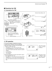
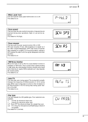
...DN] one or more times until "BK-DELAY" appears, then rotate the main dial to enter quick set mode setting (p. 45) : normal : reverse : off Microphone : UP/DN key ï CW operation q Connect a paddle or straight key as a foot switch; Delay time of 6 dots is selected. w Select CW...for all bands. (See p. 33) 1234 ˛ ˛ See p. 32 for connection details: Paddle operation from front panel MIC connector. [MICROPHONE] 5 RECEIVE AND TRANSMIT Paddle Straight key Initial set mode; to set mode for semi break-in operation is selected in quick set the desired delay...
...DN] one or more times until "BK-DELAY" appears, then rotate the main dial to enter quick set mode setting (p. 45) : normal : reverse : off Microphone : UP/DN key ï CW operation q Connect a paddle or straight key as a foot switch; Delay time of 6 dots is selected. w Select CW...for all bands. (See p. 33) 1234 ˛ ˛ See p. 32 for connection details: Paddle operation from front panel MIC connector. [MICROPHONE] 5 RECEIVE AND TRANSMIT Paddle Straight key Initial set mode; to set mode for semi break-in operation is selected in quick set the desired delay...
Instruction Manual
Page 35
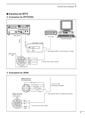
... Personal computer Rear panel view 13 9 10 11 12 5678 12 34 AF GND SQL*1 AF out SEND GND FSKK Use either the ACC or microphone connector. 13 9 10 11 12 5678 12 34 SQL*1 AF out AF in SEND GND *1Connect SQL line when required. 33 s Function for RTTY ï...
... Personal computer Rear panel view 13 9 10 11 12 5678 12 34 AF GND SQL*1 AF out SEND GND FSKK Use either the ACC or microphone connector. 13 9 10 11 12 5678 12 34 SQL*1 AF out AF in SEND GND *1Connect SQL line when required. 33 s Function for RTTY ï...
Instruction Manual
Page 44
Note that while adjusting the output power, the power meter is displayed automatically. • Mic gain This item adjusts microphone gain from L, 1 to 900 Hz in operation available. The default is 50. • VOX delay This item adjusts VOX (voice activated transmit) delay time. The ...
Note that while adjusting the output power, the power meter is displayed automatically. • Mic gain This item adjusts microphone gain from L, 1 to 900 Hz in operation available. The default is 50. • VOX delay This item adjusts VOX (voice activated transmit) delay time. The ...
Instruction Manual
Page 47
... electronic keyer use) • r : reverse (for electronic keyer use) • oF : Turns OFF the electronic keyer (for straight key use) • ud : For using the microphone's [UP]/[DN] keys insted of the dial. • Meter peak hold This item selects meter peak hold function on a signal (or 2 sec.
... electronic keyer use) • r : reverse (for electronic keyer use) • oF : Turns OFF the electronic keyer (for straight key use) • ud : For using the microphone's [UP]/[DN] keys insted of the dial. • Meter peak hold This item selects meter peak hold function on a signal (or 2 sec.
Instruction Manual
Page 56
... below 30 MHz: -50 dB, above 30 MHz: -60 dB • Carrier suppression : More than 40 dB • Unwanted sideband : More than 50 dB • Microphone connector : 8-pin connector (600 Ω) • Key connector : 3-conductor 6.5 (d) mm (1⁄4˝) • SEND/ALC connector : Phono (RCA) D Receiver • Receive system : Double-conversion superheterodyne...
... below 30 MHz: -50 dB, above 30 MHz: -60 dB • Carrier suppression : More than 40 dB • Unwanted sideband : More than 50 dB • Microphone connector : 8-pin connector (600 Ω) • Key connector : 3-conductor 6.5 (d) mm (1⁄4˝) • SEND/ALC connector : Phono (RCA) D Receiver • Receive system : Double-conversion superheterodyne...
Instruction Manual
Page 57
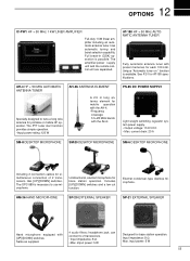
... for portable or mobile HF operation. Includes [UP]/[DOWN] switches and a low cut function. Electret condenser-type desktop microphone. Has automatic tuning and band selection capability. Full break-in (QSK) operation is possible. imput power: 5 W Designed...; current drain: 20 A SM-8 DESKTOP MICROPHONE SM-20 DESKTOP MICROPHONE SM-6 DESKTOP MICROPHONE Including 2 connection cables for base station operation. headphone jack; Unidirectional, electret microphone for simultaneous connection of 2 transceivers. input power: 5 W 55 12 OPTIONS IC-PW1 HF + 50 MHz 1 KW LINER...
... for portable or mobile HF operation. Includes [UP]/[DOWN] switches and a low cut function. Electret condenser-type desktop microphone. Has automatic tuning and band selection capability. Full break-in (QSK) operation is possible. imput power: 5 W Designed...; current drain: 20 A SM-8 DESKTOP MICROPHONE SM-20 DESKTOP MICROPHONE SM-6 DESKTOP MICROPHONE Including 2 connection cables for base station operation. headphone jack; Unidirectional, electret microphone for simultaneous connection of 2 transceivers. input power: 5 W 55 12 OPTIONS IC-PW1 HF + 50 MHz 1 KW LINER...