

Instruction Manual
Page 1
INSTRUCTION MANUAL VHF AIR BAND TRANSCEIVER iA24 iA6 This device complies with Part 15 of the FCC Rules. IC-A24 IC-A6 Operation is subject to the condition that this device does not cause harmful interference.
INSTRUCTION MANUAL VHF AIR BAND TRANSCEIVER iA24 iA6 This device complies with Part 15 of the FCC Rules. IC-A24 IC-A6 Operation is subject to the condition that this device does not cause harmful interference.
Instruction Manual
Page 3
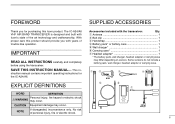
With proper care this Icom product. IMPORTANT READ ALL INSTRUCTIONS carefully and completely before using the transceiver. struction manual contains important operating instructions for purchasing this product should provide you for the IC-A24/A6. CAUTION Equipment damage may differ depending on version. .... NOTE If disregarded, inconvenience only. No risk of the art technology and craftsmanship. The IC-A24/A6 VHF AIR BAND TRANSCEIVER is designed and built with Icom's state of personal injury, fire or electric shock. ii SAVE THIS INSTRUCTION MANUAL- FOREWORD...
With proper care this Icom product. IMPORTANT READ ALL INSTRUCTIONS carefully and completely before using the transceiver. struction manual contains important operating instructions for purchasing this product should provide you for the IC-A24/A6. CAUTION Equipment damage may differ depending on version. .... NOTE If disregarded, inconvenience only. No risk of the art technology and craftsmanship. The IC-A24/A6 VHF AIR BAND TRANSCEIVER is designed and built with Icom's state of personal injury, fire or electric shock. ii SAVE THIS INSTRUCTION MANUAL- FOREWORD...

Instruction Manual
Page 5
version only 17 I "TAG" channels 17 6 VOR NAVIGATION (IC-A24 only 18 - 24 I VOR indications 18 I VOR functions 19 I Flying to a VOR station 20 I Entering a desired course 22 I Crosschecking position 22 I Weather channel scan ...selection 12 I Transferring memory contents 12 I Programming a memory channel 13 I Memory names 14 I Clearing the memory contents 14 5 SCAN OPERATION 16 - 17 I Scan types 16 I COM band scan 16 I Memory scan 16 I Duplex operation (U.S.A. version only 24 7 BATTERY PACKS 25 - 27 I Battery charging 25 I Battery cautions 25 I Optional battery case 26...
version only 17 I "TAG" channels 17 6 VOR NAVIGATION (IC-A24 only 18 - 24 I VOR indications 18 I VOR functions 19 I Flying to a VOR station 20 I Entering a desired course 22 I Crosschecking position 22 I Weather channel scan ...selection 12 I Transferring memory contents 12 I Programming a memory channel 13 I Memory names 14 I Clearing the memory contents 14 5 SCAN OPERATION 16 - 17 I Scan types 16 I COM band scan 16 I Memory scan 16 I Duplex operation (U.S.A. version only 24 7 BATTERY PACKS 25 - 27 I Battery charging 25 I Battery cautions 25 I Optional battery case 26...

Instruction Manual
Page 8
to select the 121.5 MHz emergency frequency. • DC POWER CONNECTION IC-A24/A6 CP-20 (for 11 24 V) (optional) !4 DC POWER JACK Connect the AC adapter or optional cable to charge the battery pack or to operate by ...
to select the 121.5 MHz emergency frequency. • DC POWER CONNECTION IC-A24/A6 CP-20 (for 11 24 V) (optional) !4 DC POWER JACK Connect the AC adapter or optional cable to charge the battery pack or to operate by ...
Instruction Manual
Page 9
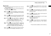
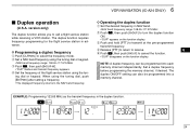
.... (p. 19)*1 PANEL DESCRIPTION 1 Push , then push [5•DUP-W] to set the displayed memory or weather channel as a "TAG" channel. (p. 17) *1 These functions available on the IC-A24 only. 4
.... (p. 19)*1 PANEL DESCRIPTION 1 Push , then push [5•DUP-W] to set the displayed memory or weather channel as a "TAG" channel. (p. 17) *1 These functions available on the IC-A24 only. 4
Instruction Manual
Page 10
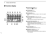
r DUPLEX INDICATOR (IC-A24 only) (p. 24) ➥"DUP" appears when the duplex function is pushed. 1 PANEL DESCRIPTION I Function display qw e r t y u !5 i !4 o !1 !3 !2 !1 !0 5 q FUNCTION INDICATOR (p. 2) Appears when is activated in use. t ...
r DUPLEX INDICATOR (IC-A24 only) (p. 24) ➥"DUP" appears when the duplex function is pushed. 1 PANEL DESCRIPTION I Function display qw e r t y u !5 i !4 o !1 !3 !2 !1 !0 5 q FUNCTION INDICATOR (p. 2) Appears when is activated in use. t ...

Instruction Manual
Page 11
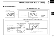
... located on a VOR radial in CDI mode. !0 MEMORY BANK NUMBER INDICATOR (p. 12) Shows the selected memory bank number. !1 OVERFLOW INDICATOR (IC-A24 only) (pgs. 18-22) Appears when the deviation between the desired course and flying course is over 10 degrees. !5 TO-FROM ...;Indicates where your actual flying course every 2 degrees. 6 o MEMORY CHANNEL INDICATOR (pgs. 12-15) Shows the memory channel number. !4 COURSE INDICATORS (IC-A24 only) (p. 19) ➥ Indicates where your aircraft is located on a course leading to the VOR station or leading away from the VOR station. !2...
... located on a VOR radial in CDI mode. !0 MEMORY BANK NUMBER INDICATOR (p. 12) Shows the selected memory bank number. !1 OVERFLOW INDICATOR (IC-A24 only) (pgs. 18-22) Appears when the deviation between the desired course and flying course is over 10 degrees. !5 TO-FROM ...;Indicates where your actual flying course every 2 degrees. 6 o MEMORY CHANNEL INDICATOR (pgs. 12-15) Shows the memory channel number. !4 COURSE INDICATORS (IC-A24 only) (p. 19) ➥ Indicates where your aircraft is located on a course leading to the VOR station or leading away from the VOR station. !2...
Instruction Manual
Page 16
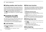
... frequency changes and • 'BEP-- 0' is OFF and 'BEP-- 9' is Max. erated. ing level. • 'ST--0' is OFF and 'ST--10' is Max. The IC-A24 and IC-A6 can be acti- to adjust the monitor- level. e Push [CLR•DEL] to turns the weather alert function ON (Indicates " ")/OFF (Indicates " "). w To turn...
... frequency changes and • 'BEP-- 0' is OFF and 'BEP-- 9' is Max. erated. ing level. • 'ST--0' is OFF and 'ST--10' is Max. The IC-A24 and IC-A6 can be acti- to adjust the monitor- level. e Push [CLR•DEL] to turns the weather alert function ON (Indicates " ")/OFF (Indicates " "). w To turn...
Instruction Manual
Page 23
Push [F] then [4 CDI]. CDI MODE General VOR equipment Function display of the IC-A24 Course indicator To-from flag indicator Two-degree deviation marks Course deviation needle 214 FROM 34 Course indicator To-from flag indicator Push [F] then [1 DVOR]. 6 VOR NAVIGATION (IC-A24 ONLY) I VOR indicators COM BAND (118.00 136.975 MHz) NAV BAND (108.00 117.975 MHz) DVOR MODE 5 Course indicator 6 To-from flag indicator Course deviation needles Overflow indicator 18
Push [F] then [4 CDI]. CDI MODE General VOR equipment Function display of the IC-A24 Course indicator To-from flag indicator Two-degree deviation marks Course deviation needle 214 FROM 34 Course indicator To-from flag indicator Push [F] then [1 DVOR]. 6 VOR NAVIGATION (IC-A24 ONLY) I VOR indicators COM BAND (118.00 136.975 MHz) NAV BAND (108.00 117.975 MHz) DVOR MODE 5 Course indicator 6 To-from flag indicator Course deviation needles Overflow indicator 18
Instruction Manual
Page 24
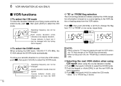
.... 19 tion's frequency. Operating frequency can not be changed . D To select the DVOR mode When entering the NAV band, 108.000-117.975 MHz, the IC-A24 selects the DVOR mode automatically. e Push , then push [4•CDI] to set the next VOR sta- Push , then push [3•FROM] or [2•TO...] to change the flag from the VOR station. 6 VOR NAVIGATION (IC-A24 ONLY) I VOR functions D To select the CDI mode To show your direction to (or from ) the VOR station, push , then push [1•DVOR] to...
.... 19 tion's frequency. Operating frequency can not be changed . D To select the DVOR mode When entering the NAV band, 108.000-117.975 MHz, the IC-A24 selects the DVOR mode automatically. e Push , then push [4•CDI] to set the next VOR sta- Push , then push [3•FROM] or [2•TO...] to change the flag from the VOR station. 6 VOR NAVIGATION (IC-A24 ONLY) I VOR functions D To select the CDI mode To show your direction to (or from ) the VOR station, push , then push [1•DVOR] to...
Instruction Manual
Page 25
... accurate (primary) VOR/CDI or landing service equipment. 20 To set the operating frequency, select the DVOR mode in advance. version only IC-A24's VOR and CDI Navigation features are supplemental aids to navigation only, and are located on a radial VOR INDICATOR NOTE from the VOR... flag when flying to select the CDI (Course De- NOTE: For U.S.A. Correct your course until 'Ω' or '≈' disap- The IC-A24 shows the deviation from a VOR station. • 'Ω' or '≈' appears to indicate your aircraft is off course from the VOR sta- lect...
... accurate (primary) VOR/CDI or landing service equipment. 20 To set the operating frequency, select the DVOR mode in advance. version only IC-A24's VOR and CDI Navigation features are supplemental aids to navigation only, and are located on a radial VOR INDICATOR NOTE from the VOR... flag when flying to select the CDI (Course De- NOTE: For U.S.A. Correct your course until 'Ω' or '≈' disap- The IC-A24 shows the deviation from a VOR station. • 'Ω' or '≈' appears to indicate your aircraft is off course from the VOR sta- lect...

Instruction Manual
Page 26
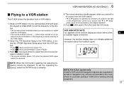
The pilot must turn more than 6 degrees right to the left. 6 VOR NAVIGATION (IC-A24 ONLY) THE AIRCRAFT IS ON COURSE THE AIRCRAFT IS OFF COURSE NOTE: The course deviation indicator appears when the aircraft is 6 degrees off course. ...
The pilot must turn more than 6 degrees right to the left. 6 VOR NAVIGATION (IC-A24 ONLY) THE AIRCRAFT IS ON COURSE THE AIRCRAFT IS OFF COURSE NOTE: The course deviation indicator appears when the aircraft is 6 degrees off course. ...
Instruction Manual
Page 27
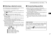
... 'FROM' flag. 22 qw er q Overflow indicator (left) w Course deviation needles (left side, select a heading minus 10 degrees. 6 VOR NAVIGATION (IC-A24 ONLY) I Entering a desired course I Crosschecking position The IC-A24 shows not only the deviation from dial. e Set the desired course to the right when your aircraft is off the...
... 'FROM' flag. 22 qw er q Overflow indicator (left) w Course deviation needles (left side, select a heading minus 10 degrees. 6 VOR NAVIGATION (IC-A24 ONLY) I Entering a desired course I Crosschecking position The IC-A24 shows not only the deviation from dial. e Set the desired course to the right when your aircraft is off the...

Instruction Manual
Page 28
6 VOR NAVIGATION (IC-A24 ONLY) EXAMPLE: Entering the desired course bearing 65° to a VOR station. CROSSCHECKING POSITION VORTAC OLYMPIA 113.4 Ch 81 OLM 310 320 330 340 350 300 290 280 270 0 10 20 30 260 40 250 50 240 60 230 VOR 70 220 station 80 210 90 200 100 190 110 180 170 160 150 140 120 130 23 310 320 330 340 350 300 290 280 270 0 10 20 30 260 40 250 50 240 60 230 VOR 70 220 station 80 210 90 200 100 190 110 180 170 160 150 140 120 130 123.65 VORTAC SEATTLE 116.8 Ch 115 SEA N Magnetic north
6 VOR NAVIGATION (IC-A24 ONLY) EXAMPLE: Entering the desired course bearing 65° to a VOR station. CROSSCHECKING POSITION VORTAC OLYMPIA 113.4 Ch 81 OLM 310 320 330 340 350 300 290 280 270 0 10 20 30 260 40 250 50 240 60 230 VOR 70 220 station 80 210 90 200 100 190 110 180 170 160 150 140 120 130 23 310 320 330 340 350 300 290 280 270 0 10 20 30 260 40 250 50 240 60 230 VOR 70 220 station 80 210 90 200 100 190 110 180 170 160 150 140 120 130 123.65 VORTAC SEATTLE 116.8 Ch 115 SEA N Magnetic north
Instruction Manual
Page 29
.... • NAV band frequency range: 108.00-117.975 MHz e Push , then push [5•DUP-W]. • "DUP" flashes and transmit frequency appears. 6 VOR NAVIGATION (IC-A24 ONLY) I Duplex operation (U.S.A. version only) D Operating the duplex function q Set the desired frequency in NAV band. • NAV band frequency range: 108.00-117...
.... • NAV band frequency range: 108.00-117.975 MHz e Push , then push [5•DUP-W]. • "DUP" flashes and transmit frequency appears. 6 VOR NAVIGATION (IC-A24 ONLY) I Duplex operation (U.S.A. version only) D Operating the duplex function q Set the desired frequency in NAV band. • NAV band frequency range: 108.00-117...

Instruction Manual
Page 31
... cable (CP-20) as I Optional battery case When using a battery case attached to the transceiver, install 6 × AA(R6) size Alkaline batteries as illustrated below . IC-A24/A6 with attached battery pack Turn power OFF CP-20 (for 8-12 hours only.
... cable (CP-20) as I Optional battery case When using a battery case attached to the transceiver, install 6 × AA(R6) size Alkaline batteries as illustrated below . IC-A24/A6 with attached battery pack Turn power OFF CP-20 (for 8-12 hours only.

Instruction Manual
Page 32
...124: Purchase separately) AC adapter 27 DC power cable (OPC-656) (Connect with AD-101. Turn power OFF BP-209N/BP-210N/ BP-211N IC-A24/A6 Check orientation and AD-99 (supplied with AD-101) AD-101 (optional) Spacer A Spacer B/C Supplied screws with the DC power supply; 13.8 ... or the DC power cable (OPC-656). 7 BATTERY PACKS I Optional battery chargers D Rapid charging with orientation as illustrated below . Turn power OFF IC-A24/A6 BP-209N/BP-210N/ BP-211N Check orientation and Spacer A AD-99 (supplied with BC-119N depending on ver- The following are additionally required. ...
...124: Purchase separately) AC adapter 27 DC power cable (OPC-656) (Connect with AD-101. Turn power OFF BP-209N/BP-210N/ BP-211N IC-A24/A6 Check orientation and AD-99 (supplied with AD-101) AD-101 (optional) Spacer A Spacer B/C Supplied screws with the DC power supply; 13.8 ... or the DC power cable (OPC-656). 7 BATTERY PACKS I Optional battery chargers D Rapid charging with orientation as illustrated below . Turn power OFF IC-A24/A6 BP-209N/BP-210N/ BP-211N Check orientation and Spacer A AD-99 (supplied with BC-119N depending on ver- The following are additionally required. ...
Instruction Manual
Page 33
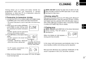
... trademarks of the master and slave transceivers. 8 CLONING Cloning allows you to quickly and easily transfer the NOTE: DO NOT transfer the data from IC-A24 to IC-A6, programmed data from one transceiver to the slave trans- SOFTWARE and the optional OPC-478 (RS-232C type) or • The master transceiver is...
... trademarks of the master and slave transceivers. 8 CLONING Cloning allows you to quickly and easily transfer the NOTE: DO NOT transfer the data from IC-A24 to IC-A6, programmed data from one transceiver to the slave trans- SOFTWARE and the optional OPC-478 (RS-232C type) or • The master transceiver is...
Instruction Manual
Page 35
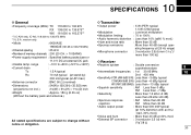
...incl.) 21⁄8(W) × 53⁄32(H) × 113⁄32(D) inch • Weight : Approx. 180 g (6.35 oz) (Without the battery pack and antenna.) COM (AM 6dB S/N): Less than -6 dBµ typical WX (FM 12dB SINAD): Less than -13 dBµ typical • Squelch sensitivity : AM Less than 0 dBµ...D General D Transmitter • Frequency coverage (MHz): TX 118.000 to 136.975 RX 108.000 to 136.975*1 WX 161.650 to 163.275*2 *1: IC-A24 only, IC-A6; 118.000 to change without notice or obligation. • External SP connector : 3-conductor 3.5 (d) mm (1/8˝)/8 Ω 30
...incl.) 21⁄8(W) × 53⁄32(H) × 113⁄32(D) inch • Weight : Approx. 180 g (6.35 oz) (Without the battery pack and antenna.) COM (AM 6dB S/N): Less than -6 dBµ typical WX (FM 12dB SINAD): Less than -13 dBµ typical • Squelch sensitivity : AM Less than 0 dBµ...D General D Transmitter • Frequency coverage (MHz): TX 118.000 to 136.975 RX 108.000 to 136.975*1 WX 161.650 to 163.275*2 *1: IC-A24 only, IC-A6; 118.000 to change without notice or obligation. • External SP connector : 3-conductor 3.5 (d) mm (1/8˝)/8 Ω 30

Instruction Manual
Page 36
... to the headset for BC-121N. D DC CABLES • CP-20 CIGARETTE LIGHTER CABLE ➥Charges the battery pack through a cigarette lighter socket*. ➥Operates IC-A24/A6 through a cigarette lighter socket*. *Both 12 V and 24 V batteries are required) simultaneously. An AC adapter is supplied with the supplied belt clip (Fixed type...
... to the headset for BC-121N. D DC CABLES • CP-20 CIGARETTE LIGHTER CABLE ➥Charges the battery pack through a cigarette lighter socket*. ➥Operates IC-A24/A6 through a cigarette lighter socket*. *Both 12 V and 24 V batteries are required) simultaneously. An AC adapter is supplied with the supplied belt clip (Fixed type...


