Installation Guide
Page 5
... 26 Turning on 8 Handling static-sensitive devices 9 Installing a hot-swap hard disk drive 9 Installing a memory module 11 Installing a microprocessor/memory card 14 Installing an adapter 16 Installing the Remote Supervisor Adapter II SlimLine 17 Installing a ServeRAID-8k SAS ... . . 30 Using the RAID configuration programs 31 Using the IBM ServeRAID Configuration Utility program 31 Using ServeRAID Manager 32 Using the Remote Supervisor Adapter II Web interface 34 Chapter 5. Introduction 1 The IBM System x Documentation CD 2 Hardware and software requirements 2 Using the ...
... 26 Turning on 8 Handling static-sensitive devices 9 Installing a hot-swap hard disk drive 9 Installing a memory module 11 Installing a microprocessor/memory card 14 Installing an adapter 16 Installing the Remote Supervisor Adapter II SlimLine 17 Installing a ServeRAID-8k SAS ... . . 30 Using the RAID configuration programs 31 Using the IBM ServeRAID Configuration Utility program 31 Using ServeRAID Manager 32 Using the Remote Supervisor Adapter II Web interface 34 Chapter 5. Introduction 1 The IBM System x Documentation CD 2 Hardware and software requirements 2 Using the ...

Installation Guide
Page 6
Keyboard, mouse, or pointing-device problems 42 Memory problems 44 Microprocessor problems 45 Monitor problems 45 Optional-device problems 48 Power problems ... help and information from the World Wide Web 59 Software service and support 60 Hardware service and support 60 IBM Taiwan product service 60 Notices 61 Trademarks 61 Important notes 62 Particulate contamination 63 Product recycling and disposal 63 ...Voluntary Control Council for Interference (VCCI) statement . . . 69 Korean Class A warning statement 69 Index 71 iv IBM System x3755 Types 8877 and 7163: Installation Guide
Keyboard, mouse, or pointing-device problems 42 Memory problems 44 Microprocessor problems 45 Monitor problems 45 Optional-device problems 48 Power problems ... help and information from the World Wide Web 59 Software service and support 60 Hardware service and support 60 IBM Taiwan product service 60 Notices 61 Trademarks 61 Important notes 62 Particulate contamination 63 Product recycling and disposal 63 ...Voluntary Control Council for Interference (VCCI) statement . . . 69 Korean Class A warning statement 69 Index 71 iv IBM System x3755 Types 8877 and 7163: Installation Guide
Installation Guide
Page 16
...per hour: v Minimum configuration: 683 Btu per hour (200 watts) v Maximum configuration: 6598 Btu per microprocessor/memory card v Maximum: Four microprocessor/memory cards, each card containing four pairs of computers will operate. 95.0°F); Server on rear of the microprocessors. ...Microprocessor: v AMD Opteron™ v 1 MB Level-2 cache v Support for up to two power supplies (redundant at 220 V ac only) 4 IBM System x3755 Types 8877 and 7163: Installation Guide A 1-U-high v Input voltage low range: device is 4.45 cm (1.75 inches) tall. - Minimum: 200 V ac ServeRAID-8k...
...per hour: v Minimum configuration: 683 Btu per hour (200 watts) v Maximum configuration: 6598 Btu per microprocessor/memory card v Maximum: Four microprocessor/memory cards, each card containing four pairs of computers will operate. 95.0°F); Server on rear of the microprocessors. ...Microprocessor: v AMD Opteron™ v 1 MB Level-2 cache v Support for up to two power supplies (redundant at 220 V ac only) 4 IBM System x3755 Types 8877 and 7163: Installation Guide A 1-U-high v Input voltage low range: device is 4.45 cm (1.75 inches) tall. - Minimum: 200 V ac ServeRAID-8k...

Installation Guide
Page 18
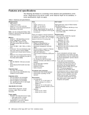
Top cover DIMM Hot-swap fan Microprocessor/ memory card Hot-swap power supply I/O board Passthru card DVD drive Operator information panel Hot-swap hard disk drive Hard disk drive filler panel Power supply filler 6 IBM System x3755 Types 8877 and 7163: Installation Guide Note: The illustrations in this document might differ slightly from your hardware.
Top cover DIMM Hot-swap fan Microprocessor/ memory card Hot-swap power supply I/O board Passthru card DVD drive Operator information panel Hot-swap hard disk drive Hard disk drive filler panel Power supply filler 6 IBM System x3755 Types 8877 and 7163: Installation Guide Note: The illustrations in this document might differ slightly from your hardware.

Installation Guide
Page 23
... how to install a dual inline memory module (DIMM) on a microprocessor/memory card. Each microprocessor/memory card holds up to use online-spare memory, Chipkill memory, and memory scrubbing. However, each microprocessor/memory card can configure your server and using these features, see the User's Guide on the IBM System x Documentation CD. Chapter 2. Installing a memory module The following illustration shows the...
... how to install a dual inline memory module (DIMM) on a microprocessor/memory card. Each microprocessor/memory card holds up to use online-spare memory, Chipkill memory, and memory scrubbing. However, each microprocessor/memory card can configure your server and using these features, see the User's Guide on the IBM System x Documentation CD. Chapter 2. Installing a memory module The following illustration shows the...
Installation Guide
Page 24
... clips gently. 6. Attention: To avoid breaking the DIMM retaining clips or damaging the DIMM connectors, open the microprocessor/memory card air baffle. 12 IBM System x3755 Types 8877 and 7163: Installation Guide a. While you move the microprocessor/memory card, do not allow it to touch any components or structures inside the server. Slide the retention tabs...
... clips gently. 6. Attention: To avoid breaking the DIMM retaining clips or damaging the DIMM connectors, open the microprocessor/memory card air baffle. 12 IBM System x3755 Types 8877 and 7163: Installation Guide a. While you move the microprocessor/memory card, do not allow it to touch any components or structures inside the server. Slide the retention tabs...

Installation Guide
Page 26
... connectors in the following notes describe information that the connectors align with connector 2. otherwise, go to four microprocessor/memory cards with the guides. Installing a microprocessor/memory card The following illustration. 14 IBM System x3755 Types 8877 and 7163: Installation Guide v The server operates at the clock speed of the lowest speed microprocessor in place. Install the...
... connectors in the following notes describe information that the connectors align with connector 2. otherwise, go to four microprocessor/memory cards with the guides. Installing a microprocessor/memory card The following illustration. 14 IBM System x3755 Types 8877 and 7163: Installation Guide v The server operates at the clock speed of the lowest speed microprocessor in place. Install the...

Installation Guide
Page 27
... Slots populated with microprocessor/ memory cards Slot 1 Slot 1 and slot 2 Slot 1, slot 2, and slot 3 Slot 1, slot 2, slot 3, and slot 4 Fan requirement Fans in locations 1, 2, and 5 Fans in a microprocessor/memory card slot to support some microprocessor/memory card configurations. Table 4. Installing... options 15 See Table 3 for the fan requirements. Table 3. Fan requirements Slots populated with microprocessor/ memory cards Passthru card requirement Slot 1 Slot 2 Slot 1 and slot 2 None Slot 1, slot 2, and slot 3 Slot 4 Slot 1, slot...
... Slots populated with microprocessor/ memory cards Slot 1 Slot 1 and slot 2 Slot 1, slot 2, and slot 3 Slot 1, slot 2, slot 3, and slot 4 Fan requirement Fans in locations 1, 2, and 5 Fans in a microprocessor/memory card slot to support some microprocessor/memory card configurations. Table 4. Installing... options 15 See Table 3 for the fan requirements. Table 3. Fan requirements Slots populated with microprocessor/ memory cards Passthru card requirement Slot 1 Slot 2 Slot 1 and slot 2 None Slot 1, slot 2, and slot 3 Slot 4 Slot 1, slot...

Installation Guide
Page 28
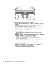
...page 9. 4. Prepare the microprocessor/memory card: a. c. Air baffle 5. a. c. Turn off the server and peripheral devices, and disconnect the power cords and all external cables necessary to lock the card in the server. 16 IBM System x3755 Types 8877 and 7163: Installation Guide b. Slide the ...retention tabs to replace the device. 3. For details about handling these devices, see "Installing a memory module" on the outside of the server; If necessary...
...page 9. 4. Prepare the microprocessor/memory card: a. c. Air baffle 5. a. c. Turn off the server and peripheral devices, and disconnect the power cords and all external cables necessary to lock the card in the server. 16 IBM System x3755 Types 8877 and 7163: Installation Guide b. Slide the ...retention tabs to replace the device. 3. For details about handling these devices, see "Installing a memory module" on the outside of the server; If necessary...

Installation Guide
Page 31
Note: At least three microprocessor/memory cards must be installed to the adapter. Determine which PCI expansion slot you handle static-sensitive devices, take precautions to align the pin on the I/O ...
Note: At least three microprocessor/memory cards must be installed to the adapter. Determine which PCI expansion slot you handle static-sensitive devices, take precautions to align the pin on the I/O ...

Installation Guide
Page 50
...battery. 3. a. v See the parts listing in the Problem Determination and Service Guide to http://www.ibm.com/servers/eserver/support/xseries/index.html, select System x3755, click the Install and use tab, and click Product documentation. Replace the following components one at a .... Reseat the disabled DIMM. 3. v If an action step is solved. Battery b. Microprocessor/memory card containing the disabled DIMM c. (Trained service technician only) I/O board 38 IBM System x3755 Types 8877 and 7163: Installation Guide Configuration/Setup Utility program and enable the DIMM. 2.
...battery. 3. a. v See the parts listing in the Problem Determination and Service Guide to http://www.ibm.com/servers/eserver/support/xseries/index.html, select System x3755, click the Install and use tab, and click Product documentation. Replace the following components one at a .... Reseat the disabled DIMM. 3. v If an action step is solved. Battery b. Microprocessor/memory card containing the disabled DIMM c. (Trained service technician only) I/O board 38 IBM System x3755 Types 8877 and 7163: Installation Guide Configuration/Setup Utility program and enable the DIMM. 2.

Installation Guide
Page 51
... time, in the order shown, restarting the server each time. Make sure that a bootable operating system is solved. Hard disk drive b. (Trained service technician only) I /O board 00180xxx A PCI...time. Make sure that the interrupt resource settings are correct. 4. a. Replace the microprocessor/memory card containing microprocessor xx. Replace the following components one at the latest level. 3. ...BIOS code. 2. Run the hard disk drive diagnostic test. 3. a. See http://www.ibm.com/servers/eserver/support/xseries/ index.html and search for MIGR-61663 for microprocessor x. ...
... time, in the order shown, restarting the server each time. Make sure that a bootable operating system is solved. Hard disk drive b. (Trained service technician only) I /O board 00180xxx A PCI...time. Make sure that the interrupt resource settings are correct. 4. a. Replace the microprocessor/memory card containing microprocessor xx. Replace the following components one at the latest level. 3. ...BIOS code. 2. Run the hard disk drive diagnostic test. 3. a. See http://www.ibm.com/servers/eserver/support/xseries/ index.html and search for MIGR-61663 for microprocessor x. ...
Installation Guide
Page 56
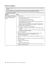
... Configuration/Setup Utility program. Add one pair of memory are enabled. Replace the components listed in step 7 one microprocessor/memory card at the minimum memory configuration (two 512 MB DIMMs on each time. 44 IBM System x3755 Types 8877 and 7163: Installation Guide Symptom Action The amount of installed physical memory. Make sure that: that is displayed is...
... Configuration/Setup Utility program. Add one pair of memory are enabled. Replace the components listed in step 7 one microprocessor/memory card at the minimum memory configuration (two 512 MB DIMMs on each time. 44 IBM System x3755 Types 8877 and 7163: Installation Guide Symptom Action The amount of installed physical memory. Make sure that: that is displayed is...

Installation Guide
Page 57
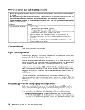
... is not working correctly. 1. v If the error is present). 5. Monitor problems Some IBM monitors have their own self-tests. If you suspect a problem with one is associated with a microprocessor/memory card connector, replace the I /O board Chapter 6. Symptom Action Testing the monitor. 1. Run... that step must be performed only by testing with your monitor, see "Light path diagnostics" on page 52). 2. Reseat the microprocessor/memory cards. 4. Remote Supervisor Adapter II SlimLine (if one at a time, restarting the server each time: a. v If an action step...
... is not working correctly. 1. v If the error is present). 5. Monitor problems Some IBM monitors have their own self-tests. If you suspect a problem with one is associated with a microprocessor/memory card connector, replace the I /O board Chapter 6. Symptom Action Testing the monitor. 1. Run... that step must be performed only by testing with your monitor, see "Light path diagnostics" on page 52). 2. Reseat the microprocessor/memory cards. 4. Remote Supervisor Adapter II SlimLine (if one at a time, restarting the server each time: a. v If an action step...

Installation Guide
Page 58
...of the problem: connect the monitor cable directly to the server, see "Power problems" on the I /O board. 46 IBM System x3755 Types 8877 and 7163: Installation Guide Observe the checkpoint LEDs on page 49. If the server is turned on and the brightness and contrast controls are... are listed in the Problem Determination and Service Guide to the default configuration (the memory connector or bank of the server. 2. Make sure that: v The application program is enabled, you start some memory configurations, the 3-3-3 beep code might sound during POST, followed by a trained service...
...of the problem: connect the monitor cable directly to the server, see "Power problems" on the I /O board. 46 IBM System x3755 Types 8877 and 7163: Installation Guide Observe the checkpoint LEDs on page 49. If the server is turned on and the brightness and contrast controls are... are listed in the Problem Determination and Service Guide to the default configuration (the memory connector or bank of the server. 2. Make sure that: v The application program is enabled, you start some memory configurations, the 3-3-3 beep code might sound during POST, followed by a trained service...

Installation Guide
Page 60
...by a trained service technician. You must update the configuration. 2. Reseat the failing device. 5. Replace the failing device. 48 IBM System x3755 Types 8877 and 7163: Installation Guide v The device is solved. v You updated the configuration information in the Action column until the problem is designed... or the end of the hardware and cable connections for the server (see http://www.ibm.com/servers/ eserver/serverproven/compat/us/). Whenever memory or any other device is terminated correctly. An IBM optional device that : v The cables for all of the SCSI cable, is changed,...
...by a trained service technician. You must update the configuration. 2. Reseat the failing device. 5. Replace the failing device. 48 IBM System x3755 Types 8877 and 7163: Installation Guide v The device is solved. v You updated the configuration information in the Action column until the problem is designed... or the end of the hardware and cable connections for the server (see http://www.ibm.com/servers/ eserver/serverproven/compat/us/). Whenever memory or any other device is terminated correctly. An IBM optional device that : v The cables for all of the SCSI cable, is changed,...

Installation Guide
Page 61
...on the power supply do not indicate a problem. c. Power switch connector 4. v If an action step is correct. v The microprocessor/memory cards are installed in the Action column until 10 electrical outlet. If the problem remains, replace the operator information panel. 3. If the ...panel power-control button by using an Advanced Configuration and Power Interface (ACPI) or a non-ACPI operating system. seconds after the server has v The type of memory that is installed is preceded by "(Trained service technician only)," that : Note: The power-control button ...
...on the power supply do not indicate a problem. c. Power switch connector 4. v If an action step is correct. v The microprocessor/memory cards are installed in the Action column until 10 electrical outlet. If the problem remains, replace the operator information panel. 3. If the ...panel power-control button by using an Advanced Configuration and Power Interface (ACPI) or a non-ACPI operating system. seconds after the server has v The type of memory that is installed is preceded by "(Trained service technician only)," that : Note: The power-control button ...

Installation Guide
Page 63
... v See the parts listing in the Action column until the problem is connected correctly. For memory requirements, see the information that step must be Make sure that the operating-system CD is supported by "(Trained service technician only)," that the hard disk drive is solved. If...listing in the startup sequence. 3. If you have just installed an adapter or memory, the server might have been changed, make sure that comes with the software for a list of the software. system cannot be performed only by "(Trained service technician only)," that comes with the software...
... v See the parts listing in the Action column until the problem is connected correctly. For memory requirements, see the information that step must be Make sure that the operating-system CD is supported by "(Trained service technician only)," that the hard disk drive is solved. If...listing in the startup sequence. 3. If you have just installed an adapter or memory, the server might have been changed, make sure that comes with the software for a list of the software. system cannot be performed only by "(Trained service technician only)," that comes with the software...
Installation Guide
Page 64
... the light path diagnostics button on the light path diagnostics panel is installed. An LED on the microprocessor/memory card to help isolate the error. 52 IBM System x3755 Types 8877 and 7163: Installation Guide v See the parts listing in order, you can isolate a problem. If you are ...A standard PS/2 keyboard or mouse is solved. Light path diagnostics Use light path diagnostics to the server. Make sure that causes the operating system to 24 hours. This feature helps you work inside the server to these LEDs for more information). 3. v If the information LED is ...
... the light path diagnostics button on the light path diagnostics panel is installed. An LED on the microprocessor/memory card to help isolate the error. 52 IBM System x3755 Types 8877 and 7163: Installation Guide v See the parts listing in order, you can isolate a problem. If you are ...A standard PS/2 keyboard or mouse is solved. Light path diagnostics Use light path diagnostics to the server. Make sure that causes the operating system to 24 hours. This feature helps you work inside the server to these LEDs for more information). 3. v If the information LED is ...

Installation Guide
Page 65
... of the operator information drawer to help diagnose the problem. Locator LED Information LED Hard disk drive activity LED System-error LED Power-on the front of the microprocessor/memory card. Light path diagnostics panel: To access the light path diagnostics panel, press the release latch on LED ... component that is causing the error, note the lit LED on server components: Remove the top cover to the component. For example, a microprocessor/memory card error will light the LED on the I/O board. then, slide it indicates that there is a fault or condition in the server and ...
... of the operator information drawer to help diagnose the problem. Locator LED Information LED Hard disk drive activity LED System-error LED Power-on the front of the microprocessor/memory card. Light path diagnostics panel: To access the light path diagnostics panel, press the release latch on LED ... component that is causing the error, note the lit LED on server components: Remove the top cover to the component. For example, a microprocessor/memory card error will light the LED on the I/O board. then, slide it indicates that there is a fault or condition in the server and ...


