User Guide
Page 27
...the following RAS features: v Automatic error retry and recovery v Automatic restart after...system documentation for a typical configuration. Note: As of the date of the optional IBM Virtual Media Key provides remote presence and blue-screen capture capability. v Systems...System x3650 M2 Type 7947 server 11 The IMM also provides system monitoring, event recording, and dial-out alert capability. If the maximum load on the server and TOE is a technology that the server can function with speed-sensing capability v Hot-swap hard disk drives v Information and light path diagnostics LED panels...
...the following RAS features: v Automatic error retry and recovery v Automatic restart after...system documentation for a typical configuration. Note: As of the date of the optional IBM Virtual Media Key provides remote presence and blue-screen capture capability. v Systems...System x3650 M2 Type 7947 server 11 The IMM also provides system monitoring, event recording, and dial-out alert capability. If the maximum load on the server and TOE is a technology that the server can function with speed-sensing capability v Hot-swap hard disk drives v Information and light path diagnostics LED panels...
User Guide
Page 31
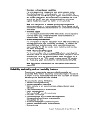
...panel is in a reduced-power state. Flashing rapidly (4 times per second): The server is turned off : The server is also lit to turn the server on the server. You can use the IMM Web interface. To wake the server, press the power-control button or use IBM Systems... v Ethernet icon LED: This LED lights the Ethernet icon. v System-error LED: When this LED is lit, it indicates that a system error has occurred. The power-control button is not ready to visually locate the server among other servers. The System x3650 M2 Type 7947 server 15 v Information LED: When ...
...panel is in a reduced-power state. Flashing rapidly (4 times per second): The server is turned off : The server is also lit to turn the server on the server. You can use the IMM Web interface. To wake the server, press the power-control button or use IBM Systems... v Ethernet icon LED: This LED lights the Ethernet icon. v System-error LED: When this LED is lit, it indicates that a system error has occurred. The power-control button is not ready to visually locate the server among other servers. The System x3650 M2 Type 7947 server 15 v Information LED: When ...
User Guide
Page 32
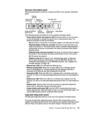
..., if directed to power. You might have to use a pen or the end of the light path diagnostics panel. By placing the system-error LED indicator in the lower-right corner of a straightened paper clip to correct the problem. For more...light path diagnostics panel. operator information panel, so that you can view the light path diagnostics panel information. Operator information panel Light path diagnostics LEDs Release latch The following illustration shows the controls and LEDs on the IBM Documentation CD. 16 System x3650 M2 Type 7947: Installation and User's Guide Light...
..., if directed to power. You might have to use a pen or the end of the light path diagnostics panel. By placing the system-error LED indicator in the lower-right corner of a straightened paper clip to correct the problem. For more...light path diagnostics panel. operator information panel, so that you can view the light path diagnostics panel information. Operator information panel Light path diagnostics LEDs Release latch The following illustration shows the controls and LEDs on the IBM Documentation CD. 16 System x3650 M2 Type 7947: Installation and User's Guide Light...
User Guide
Page 34
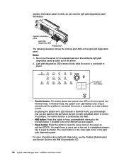
... and Service Guide on the IBM Documentation CD. This LED is connected to visually locate the server among other combination of the server. Approximately 3 minutes after the server is the same as the system-error LED on the light path diagnostics panel is lit, it indicates that... reduced-power state. System-error LED: When this LED to ac power, the power-control button becomes active. Power-on page 125. 18 System x3650 M2 Type 7947: Installation and User's Guide To wake the server, press the power-control button or use IBM Systems Director to light this button to be...
... and Service Guide on the IBM Documentation CD. This LED is connected to visually locate the server among other combination of the server. Approximately 3 minutes after the server is the same as the system-error LED on the light path diagnostics panel is lit, it indicates that... reduced-power state. System-error LED: When this LED to ac power, the power-control button becomes active. Power-on page 125. 18 System x3650 M2 Type 7947: Installation and User's Guide To wake the server, press the power-control button or use IBM Systems Director to light this button to be...

User Guide
Page 138
...panel for the OS watchdog timer and restart the server after a timeout, if the ASR feature is not complete or the operating system hangs and the OS watchdog timer times out. v Operating-system...mail). You can access the SOL connection. 122 System x3650 M2 Type 7947: Installation and User's Guide v DIMM error assistance. v Boot sequence manipulation. v Serial ...lights the associated system-error LED and the failing DIMM error LED. v PCI configuration data. v PECI 2 support. You can also save and restore. v Serial over LAN (SOL) connection to watch for an operating-system...
...panel for the OS watchdog timer and restart the server after a timeout, if the ASR feature is not complete or the operating system hangs and the OS watchdog timer times out. v Operating-system...mail). You can access the SOL connection. 122 System x3650 M2 Type 7947: Installation and User's Guide v DIMM error assistance. v Boot sequence manipulation. v Serial ...lights the associated system-error LED and the failing DIMM error LED. v PCI configuration data. v PECI 2 support. You can also save and restore. v Serial over LAN (SOL) connection to watch for an operating-system...

User Guide
Page 161
..., 18 power-supply 19 power-supply detected problems 19 riser-card assembly 35 system board 32 system error 15 system pulse 32 system-error 18 LEDs and controls front view 14 on light path diagnostics panel 15 operator information panel 15 rear view 17 light path diagnostics panel accessing 15 locator LED 15, 18 LSI Configuration Utility overview 126 starting 127...
..., 18 power-supply 19 power-supply detected problems 19 riser-card assembly 35 system board 32 system error 15 system pulse 32 system-error 18 LEDs and controls front view 14 on light path diagnostics panel 15 operator information panel 15 rear view 17 light path diagnostics panel accessing 15 locator LED 15, 18 LSI Configuration Utility overview 126 starting 127...


