
Hardware Maintenance Manual
Page 58
...hard drive cables. 4. Note: When replacing the hard disk drive, make sure you obtain the proper Recovery CD to the appropriate section. What to "Types 8307, 8308, 8310, 8311, 8314, and 8315" on the front of the computer. This will detach the hard drive. 2. Remove the 4 screws securing the... hard drive inside the hard drive cage and slide the drive out of the computer. 3. Install the adapter-slot-cover latch. Installing internal drives Types 8301 and 8302 ...
...hard drive cables. 4. Note: When replacing the hard disk drive, make sure you obtain the proper Recovery CD to the appropriate section. What to "Types 8307, 8308, 8310, 8311, 8314, and 8315" on the front of the computer. This will detach the hard drive. 2. Remove the 4 screws securing the... hard drive inside the hard drive cage and slide the drive out of the computer. 3. Install the adapter-slot-cover latch. Installing internal drives Types 8301 and 8302 ...

Hardware Maintenance Manual
Page 74
...of the cover. 3. To update the configuration, see "Setup Utility program" on page 31. 5. Types 8307, 8308, 8310, 8311, 8314, and 8315 After working with options, you need to install any removed ...correctly and that no tools or loose screws are left inside your computer. 2. Ensure that all components have been reassembled correctly and that no tools or... and reconnect any cables that is installed, you might need to confirm the updated information in the IBM Setup Utility program. Clear any cables, including telephone lines and power cords. To update the configuration,...
...of the cover. 3. To update the configuration, see "Setup Utility program" on page 31. 5. Types 8307, 8308, 8310, 8311, 8314, and 8315 After working with options, you need to install any removed ...correctly and that no tools or loose screws are left inside your computer. 2. Ensure that all components have been reassembled correctly and that no tools or... and reconnect any cables that is installed, you might need to confirm the updated information in the IBM Setup Utility program. Clear any cables, including telephone lines and power cords. To update the configuration,...

Hardware Maintenance Manual
Page 75
... page 31. 5. This is a normal sequence to enable the computer to the computer. depending on the option that no tools or loose screws are left inside your computer: 1. Installing Options 69 Ensure that all components have been reassembled correctly and that is first plugged in, the computer might need to turn... off. See "Installing external options" on page 24. Important: When the power cord is installed, you might appear to confirm the updated information in the IBM Setup Utility program.
... page 31. 5. This is a normal sequence to enable the computer to the computer. depending on the option that no tools or loose screws are left inside your computer: 1. Installing Options 69 Ensure that all components have been reassembled correctly and that is first plugged in, the computer might need to turn... off. See "Installing external options" on page 24. Important: When the power cord is installed, you might appear to confirm the updated information in the IBM Setup Utility program.

Hardware Maintenance Manual
Page 89
...ensure that attach the system board to confirm the updated information in the IBM Setup Utility program. Disconnect all external cables and power cords; To replace the cover and connect cables to : Chapter 6. FRU Removals 83 Types 8307, 8308, 8310, 8311, 8314, and 8315 To remove the system ...board, do the following: 1. Remove the six screws that these cable routing measures are left inside the computer. 2. See "Types 8307, 8308, 8310, 8311, 8314, and 8315" on page 41. 2. Lift out the system board. Replacing the cover, Types 8301 and...
...ensure that attach the system board to confirm the updated information in the IBM Setup Utility program. Disconnect all external cables and power cords; To replace the cover and connect cables to : Chapter 6. FRU Removals 83 Types 8307, 8308, 8310, 8311, 8314, and 8315 To remove the system ...board, do the following: 1. Remove the six screws that these cable routing measures are left inside the computer. 2. See "Types 8307, 8308, 8310, 8311, 8314, and 8315" on page 41. 2. Lift out the system board. Replacing the cover, Types 8301 and...

Hardware Maintenance Manual
Page 129
...) Tape automatically ejected from drive 1. SCSI Adapter or System Board 216XX 1. Remove redundant adapters, run Auto Configuration program, then retest. Tape Drive 2. Verify drive switches inside cover are set in drive. SCSI Cable (internal) 4. Rotary Switch Circuit Board 2. ISDN/2 Wrap Plug 3. Riser card 27502, 27504, 27510, 27511, 27533, 27534, 27536, 27537...
...) Tape automatically ejected from drive 1. SCSI Adapter or System Board 216XX 1. Remove redundant adapters, run Auto Configuration program, then retest. Tape Drive 2. Verify drive switches inside cover are set in drive. SCSI Cable (internal) 4. Rotary Switch Circuit Board 2. ISDN/2 Wrap Plug 3. Riser card 27502, 27504, 27510, 27511, 27533, 27534, 27536, 27537...

Hardware Maintenance Manual
Page 272
Flash from Operating System (WinPhlash) Attention: Refer to the information label located inside the system unit cover for any model-specific information. 1. Click Finish. You will locate the 24jyNNusa.exe file you just downloaded. 5. Click Start, then ... system will automatically shutdown and restart so that the changes will be prompted with new settings. 16. This will told to the information label located inside the system unit cover for any model-specific information. 1. Click I Agree. You will locate the 24jyNNusa.exe file you just downloaded. 5. Flash from the ...
Flash from Operating System (WinPhlash) Attention: Refer to the information label located inside the system unit cover for any model-specific information. 1. Click Finish. You will locate the 24jyNNusa.exe file you just downloaded. 5. Click Start, then ... system will automatically shutdown and restart so that the changes will be prompted with new settings. 16. This will told to the information label located inside the system unit cover for any model-specific information. 1. Click I Agree. You will locate the 24jyNNusa.exe file you just downloaded. 5. Flash from the ...

Hardware Maintenance Manual
Page 273
...; 10. For example, press 1 for creating a CD from CD image. You will be asked if you wish to "Types 8307, 8308, 8310, 8311, 8314, and 8315" on page 46 or the label inside the computer for further assistance. 12. Wait until you are prompted to select a country, press the number on the...
...; 10. For example, press 1 for creating a CD from CD image. You will be asked if you wish to "Types 8307, 8308, 8310, 8311, 8314, and 8315" on page 46 or the label inside the computer for further assistance. 12. Wait until you are prompted to select a country, press the number on the...

Hardware Maintenance Manual
Page 277
... all safety shields, guards, labels, and ground wires. Use a slow lifting force. v Before you can be hazardous to the customer. © Copyright IBM Corp. 2001 271 Ensure that your sleeves are fastened or rolled up with the assumption that you need to help you are too heavy for... muscles; General safety Follow these rules to lift any other parts in a safe place, away from the end. v Keep your necktie or scarf inside clothing or fasten it with a nonconductive clip, approximately 8 centimeters (3 inches) from all computers, or that are not in this action removes the ...
... all safety shields, guards, labels, and ground wires. Use a slow lifting force. v Before you can be hazardous to the customer. © Copyright IBM Corp. 2001 271 Ensure that your sleeves are fastened or rolled up with the assumption that you need to help you are too heavy for... muscles; General safety Follow these rules to lift any other parts in a safe place, away from the end. v Keep your necktie or scarf inside clothing or fasten it with a nonconductive clip, approximately 8 centimeters (3 inches) from all computers, or that are not in this action removes the ...
Hardware Maintenance Manual
Page 280
...sensitive to provide a static-free work mat, and the person handling the part are wearing a wrist strap. Remove the cover. 5. Check inside the unit for 0.1 ohm or less between objects. Protect against your skin to measure third-wire ground continuity for any obvious non... or rivets) have been certified (ISO 9000) as metal filings, contamination, water or other people. v Select a grounding system, such as to any non-IBM alterations. 6. a. Check for any obvious unsafe conditions, such as fully effective. v Prevent the part from touching your body. Note: The use of any ...
...sensitive to provide a static-free work mat, and the person handling the part are wearing a wrist strap. Remove the cover. 5. Check inside the unit for 0.1 ohm or less between objects. Protect against your skin to measure third-wire ground continuity for any obvious non... or rivets) have been certified (ISO 9000) as metal filings, contamination, water or other people. v Select a grounding system, such as to any non-IBM alterations. 6. a. Check for any obvious unsafe conditions, such as fully effective. v Prevent the part from touching your body. Note: The use of any ...

Hardware Maintenance Manual
Page 282
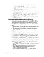
... v Repair or disassemble Dispose of the battery as CD-ROMs, DVD-ROM drives, fiber optic devices, or transmitters) are no serviceable parts inside the device. The battery contains lithium and can explode if not properly used, handled, or disposed of the laser product could result in hazardous...the beam, do not view directly with the same module type made by the manufacturer. CAUTION: When replacing the lithium battery, use only IBM Part Number 33F8354 or an equivalent type battery recommended by the same manufacturer. If your system has a module containing a lithium battery, replace...
... v Repair or disassemble Dispose of the battery as CD-ROMs, DVD-ROM drives, fiber optic devices, or transmitters) are no serviceable parts inside the device. The battery contains lithium and can explode if not properly used, handled, or disposed of the laser product could result in hazardous...the beam, do not view directly with the same module type made by the manufacturer. CAUTION: When replacing the lithium battery, use only IBM Part Number 33F8354 or an equivalent type battery recommended by the same manufacturer. If your system has a module containing a lithium battery, replace...