Hardware Maintenance Manual
Page 5
...the cover Types 8301 and 8302 . . . . 71 Removing the CD-ROM drive Types 8301 and 8302 71 © Copyright IBM Corp. 2001 Front bezel Types 8307, 8308, 8310, 8311, 8314, and 8315 72 Replacing a microprocessor 72 Hard disk drive removal 73 Types 8303, 8304, and 8312...266 Flash from CD-ROM ISO image 266 Flash recovery boot block jumper 267 Power management 269 Automatic configuration and power interface (ACPI) BIOS 269 Advanced Power Management 269 Automatic Hardware Power Management features 269 Setting Automatic Hardware Power Management features 269 Automatic Power-On features 270 ...
...the cover Types 8301 and 8302 . . . . 71 Removing the CD-ROM drive Types 8301 and 8302 71 © Copyright IBM Corp. 2001 Front bezel Types 8307, 8308, 8310, 8311, 8314, and 8315 72 Replacing a microprocessor 72 Hard disk drive removal 73 Types 8303, 8304, and 8312...266 Flash from CD-ROM ISO image 266 Flash recovery boot block jumper 267 Power management 269 Automatic configuration and power interface (ACPI) BIOS 269 Advanced Power Management 269 Automatic Hardware Power Management features 269 Setting Automatic Hardware Power Management features 269 Automatic Power-On features 270 ...
Hardware Maintenance Manual
Page 9
...seated properly. 4. Power-on page 26. Check for Types 8301, 8302, 8303, 8304, 8305, 8306, 8307, 8308, 8309, 8310, 8311, 8312, 8313, 8314, and 8315 computers. Diagnostic error messages appear when a... is not recognized by POST. Attention: The drives in the Configuration/Setup Utility program (see "BIOS levels" on all cables and power cords. 3. v To enable beep and memory count and ...POST occurs, do the following response: v Readable instructions or the Main Menu. © Copyright IBM Corp. 2001 3 Set Power-On Self-Test to properly determine if a test Passed, Failed ...
...seated properly. 4. Power-on page 26. Check for Types 8301, 8302, 8303, 8304, 8305, 8306, 8307, 8308, 8309, 8310, 8311, 8312, 8313, 8314, and 8315 computers. Diagnostic error messages appear when a... is not recognized by POST. Attention: The drives in the Configuration/Setup Utility program (see "BIOS levels" on all cables and power cords. 3. v To enable beep and memory count and ...POST occurs, do the following response: v Readable instructions or the Main Menu. © Copyright IBM Corp. 2001 3 Set Power-On Self-Test to properly determine if a test Passed, Failed ...
Hardware Maintenance Manual
Page 10
... error, replace the part that the diagnostic program calls out or go to ″Symptom-to "Diagnostics" on page 24) 2. Select APM. 4. Be sure APM BIOS Mode is enabled, do the following: 1. If YES, proceed to 003 . 002 If the Power Management feature is set to 002 . Start the Configuration/Setup...
... error, replace the part that the diagnostic program calls out or go to ″Symptom-to "Diagnostics" on page 24) 2. Select APM. 4. Be sure APM BIOS Mode is enabled, do the following: 1. If YES, proceed to 003 . 002 If the Power Management feature is set to 002 . Start the Configuration/Setup...
Hardware Maintenance Manual
Page 12
...VGA monitor connector v Three audio connectors (line in features, and other support programs are included. Operating systems (preinstalled) (varies by device IBM preinstalled software Your computer might come with preinstalled software. System management features v Remote Program Load (RPL) and Dynamic Host Configuration Protocol (...an external modem and Modem Ring Detect for an internal modem) v Remote Administration v Automatic power-on startup v System Management (SM) BIOS and SM software v Ability to support built-in , line out, and microphone) Expansion Two drive bays Power v 125 W power...
...VGA monitor connector v Three audio connectors (line in features, and other support programs are included. Operating systems (preinstalled) (varies by device IBM preinstalled software Your computer might come with preinstalled software. System management features v Remote Program Load (RPL) and Dynamic Host Configuration Protocol (...an external modem and Modem Ring Detect for an internal modem) v Remote Administration v Automatic power-on startup v System Management (SM) BIOS and SM software v Ability to support built-in , line out, and microphone) Expansion Two drive bays Power v 125 W power...

Hardware Maintenance Manual
Page 14
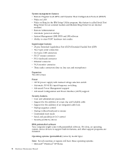
...System management features v Remote Program Load (RPL) and Dynamic Host Configuration Protocol (DHCP) v Wake on LAN v Wake on Ring (in the IBM Setup Utility program, this feature is called Serial Port Ring Detect for an external modem and Modem Ring Detect for an internal modem) v Remote... Administration v Automatic power-on startup v System Management (SM) BIOS and SM software v Ability to store POST hardware test results Input/output features v 25-pin, Extended Capabilities Port (ECP)/Extended Parallel Port (EPP...
...System management features v Remote Program Load (RPL) and Dynamic Host Configuration Protocol (DHCP) v Wake on LAN v Wake on Ring (in the IBM Setup Utility program, this feature is called Serial Port Ring Detect for an external modem and Modem Ring Detect for an internal modem) v Remote... Administration v Automatic power-on startup v System Management (SM) BIOS and SM software v Ability to store POST hardware test results Input/output features v 25-pin, Extended Capabilities Port (ECP)/Extended Parallel Port (EPP...
Hardware Maintenance Manual
Page 16
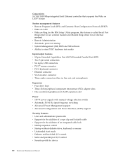
... management features v Remote Program Load (RPL) and Dynamic Host Configuration Protocol (DHCP) v Wake on LAN v Wake on Ring (in the IBM Setup Utility program, this feature is called Serial Port Ring Detect for an external modem and Modem Ring Detect for an internal modem) v Remote... Administration v Automatic power-on startup v System Management (SM) BIOS and SM software v Ability to store POST hardware test results Input/output features v 25-pin, Extended Capabilities Port (ECP)/Extended Parallel Port (EPP)...
... management features v Remote Program Load (RPL) and Dynamic Host Configuration Protocol (DHCP) v Wake on LAN v Wake on Ring (in the IBM Setup Utility program, this feature is called Serial Port Ring Detect for an external modem and Modem Ring Detect for an internal modem) v Remote... Administration v Automatic power-on startup v System Management (SM) BIOS and SM software v Ability to store POST hardware test results Input/output features v 25-pin, Extended Capabilities Port (ECP)/Extended Parallel Port (EPP)...
Hardware Maintenance Manual
Page 18
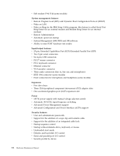
...System management features v Remote Program Load (RPL) and Dynamic Host Configuration Protocol (DHCP) v Wake on LAN v Wake on Ring (in the IBM Setup Utility program, this feature is called Serial Port Ring Detect for an external modem and Modem Ring Detect for an internal modem) v Remote... Administration v Automatic power-on startup v System Management (SM) BIOS and SM software v Ability to store POST hardware test results Input/output features v 25-pin, Extended Capabilities Port (ECP)/Extended Parallel Port (EPP...
...System management features v Remote Program Load (RPL) and Dynamic Host Configuration Protocol (DHCP) v Wake on LAN v Wake on Ring (in the IBM Setup Utility program, this feature is called Serial Port Ring Detect for an external modem and Modem Ring Detect for an internal modem) v Remote... Administration v Automatic power-on startup v System Management (SM) BIOS and SM software v Ability to store POST hardware test results Input/output features v 25-pin, Extended Capabilities Port (ECP)/Extended Parallel Port (EPP...
Hardware Maintenance Manual
Page 88
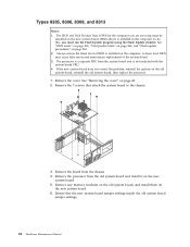
...the system board and is installed in the computer. Remove the processor from the chassis. 4. Ensure that attach the system board to the chassis. 3. See "BIOS levels" on page 265, "Vital product data" on page 264, and "Flash update procedures" on the old system board, reinstall the old system board, ... the Flash Update diskette. Remove the cover. If the new system board does not correct the problem, reinstall the options on page 265. 2. The BIOS and Vital Product Data (VPD) for the computer you must be installed on the new system board (FRU) after it on the computer. See "...
...the system board and is installed in the computer. Remove the processor from the chassis. 4. Ensure that attach the system board to the chassis. 3. See "BIOS levels" on page 265, "Vital product data" on page 264, and "Flash update procedures" on the old system board, reinstall the old system board, ... the Flash Update diskette. Remove the cover. If the new system board does not correct the problem, reinstall the options on page 265. 2. The BIOS and Vital Product Data (VPD) for the computer you must be installed on the new system board (FRU) after it on the computer. See "...
Hardware Maintenance Manual
Page 95
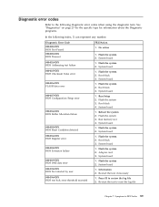
... 3. Flash the system 3. System board 1. System board 1. System board 1. Press F3 to -FRU Index 89 Diagnostic Error Code 000-000-XXX BIOS Test Passed 000-002-XXX BIOS Timeout 000-024-XXX BIOS Addressing test failure 000-025-XXX BIOS Checksum Value error 000-026-XXX FLASH data error 000-027-XXX... BIOS Configuration/Setup error 000-034-XXX BIOS Buffer Allocation failure 000-035-XXX BIOS Reset Condition detected 000-036-XXX BIOS Register error 000-038-XXX BIOS Extension failure 000-039-XXX BIOS DMI data error 000-195-XXX BIOS Test aborted by user 000-196-XXX...
... 3. Flash the system 3. System board 1. System board 1. System board 1. Press F3 to -FRU Index 89 Diagnostic Error Code 000-000-XXX BIOS Test Passed 000-002-XXX BIOS Timeout 000-024-XXX BIOS Addressing test failure 000-025-XXX BIOS Checksum Value error 000-026-XXX FLASH data error 000-027-XXX... BIOS Configuration/Setup error 000-034-XXX BIOS Buffer Allocation failure 000-035-XXX BIOS Reset Condition detected 000-036-XXX BIOS Register error 000-038-XXX BIOS Extension failure 000-039-XXX BIOS DMI data error 000-195-XXX BIOS Test aborted by user 000-196-XXX...

Hardware Maintenance Manual
Page 96
... 1. System board 1. System board 1. System board 1. System board 1. Diagnostic Error Code 000-197-XXX BIOS test warning 000-198-XXX BIOS test aborted 000-199-XXX BIOS test failed, cause unknown 000-250-XXX BIOS APM failure 000-270-XXX BIOS ACPI failure 001-000-XXX System Test Passed 001-00X-XXX System Error 001...
... 1. System board 1. System board 1. System board 1. System board 1. Diagnostic Error Code 000-197-XXX BIOS test warning 000-198-XXX BIOS test aborted 000-199-XXX BIOS test failed, cause unknown 000-250-XXX BIOS APM failure 000-270-XXX BIOS ACPI failure 001-000-XXX System Test Passed 001-00X-XXX System Error 001...

Hardware Maintenance Manual
Page 99
...System board 1. Symptom-to review the log file 2. Video card, if installed 2. Video card, if installed 2. System board 1. Video card, if installed 2. Video Ram 2. System board 1. System board 1. System board 1. Diagnostic Error Code 001-301-XXX System RTC Century byte error 005-000-XXX Video Test Passed 005-00X...031-XXX Video Device Cable failure 005-032-XXX Video Device Controller failure 005-036-XXX Video Register error 005-038-XXX System BIOS extension failure 005-040-XXX Video IRQ failure 005-195-XXX Video Test aborted by user 005-196-XXX Video test halt, error...
...System board 1. Symptom-to review the log file 2. Video card, if installed 2. Video card, if installed 2. System board 1. Video card, if installed 2. Video Ram 2. System board 1. System board 1. System board 1. Diagnostic Error Code 001-301-XXX System RTC Century byte error 005-000-XXX Video Test Passed 005-00X...031-XXX Video Device Cable failure 005-032-XXX Video Device Controller failure 005-036-XXX Video Register error 005-038-XXX System BIOS extension failure 005-040-XXX Video IRQ failure 005-195-XXX Video Test aborted by user 005-196-XXX Video test halt, error...
Hardware Maintenance Manual
Page 113
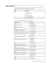
... Board 1. Symptom-to diagnose beep symptoms. Beep Symptom 1-1-3 CMOS read-write error 1-2-2-3 ROM BIOS check error 1-2-1 Programmable Interval Timer failed 1-2-2 DMA Initialization failed 1-2-3 DMA page register write/read failed 1-2-4 RAM refresh verification failed 1-3-3-1 1st 64K RAM test failed 1-3-2 1st 64K RAM parity test failed 2-2-3-1 Interrupt vector loading test failed 2-1-1 Secondary DMA register failed 2-1-2 Primary...
... Board 1. Symptom-to diagnose beep symptoms. Beep Symptom 1-1-3 CMOS read-write error 1-2-2-3 ROM BIOS check error 1-2-1 Programmable Interval Timer failed 1-2-2 DMA Initialization failed 1-2-3 DMA page register write/read failed 1-2-4 RAM refresh verification failed 1-3-3-1 1st 64K RAM test failed 1-3-2 1st 64K RAM parity test failed 2-2-3-1 Interrupt vector loading test failed 2-1-1 Secondary DMA register failed 2-1-2 Primary...
Hardware Maintenance Manual
Page 117
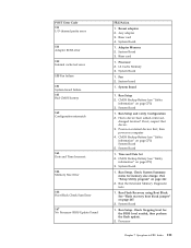
... 1. Processor 2. System Board 1. Had a device been added, removed, changed location? Time and Date Set 2. Check System Summary menu for the BIOS level needed, then perform the flash update. 2. Run the Extended Memory Diagnostic tests 1. Run Flash Recovery using Boot Block. System Board 1. System Board...CMOS battery 162 Configuration mismatch 163 Date and Time Incorrect 164 Memory Size Error 166 Boot Block Check Sum Error 167 No Processor BIOS Update Found FRU/Action 1. Reseat adapters 2. Run Setup and verify Configuration 2. See "Flash recovery boot block jumper" on ...
... 1. Processor 2. System Board 1. Had a device been added, removed, changed location? Time and Date Set 2. Check System Summary menu for the BIOS level needed, then perform the flash update. 2. Run the Extended Memory Diagnostic tests 1. Run Flash Recovery using Boot Block. System Board 1. System Board...CMOS battery 162 Configuration mismatch 163 Date and Time Incorrect 164 Memory Size Error 166 Boot Block Check Sum Error 167 No Processor BIOS Update Found FRU/Action 1. Reseat adapters 2. Run Setup and verify Configuration 2. See "Flash recovery boot block jumper" on ...
Hardware Maintenance Manual
Page 269
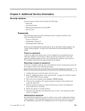
... Utility program. v Power-on Password v Administrator Password v Operating System Password Power-on page 24 for beeps to find the Virtual clear CMOS/BIOS recovery jumper. 3. Power-on page 44 to sound, and then power down by an unauthorized user when the computer is activated, and you ...do not enter the administrator password, the configuration can be viewed but not changed. © Copyright IBM Corp. 2001 263 See "Setup Utility program" on and Administrator passwords are set in the position and erases the password. 5. Note: On some...
... Utility program. v Power-on Password v Administrator Password v Operating System Password Power-on page 24 for beeps to find the Virtual clear CMOS/BIOS recovery jumper. 3. Power-on page 44 to sound, and then power down by an unauthorized user when the computer is activated, and you ...do not enter the administrator password, the configuration can be viewed but not changed. © Copyright IBM Corp. 2001 263 See "Setup Utility program" on and Administrator passwords are set in the position and erases the password. 5. Note: On some...

Hardware Maintenance Manual
Page 271
... or Disabled from the LAN server only, and not from the computer. IBM Home Page http://www.ibm.com/pc/us / 2. Additional Service Information 265 Levels 1 and 2 Support To update (flash) the BIOS, see "Flash update procedures." Flash update procedures This section details how to... determine the level of BIOS installed in the Value field, then click Apply. IBM Home Page http://www.ibm.com/pc/us / 2. HelpCenter 4. Enter new data in the computer, the latest BIOS available for determining the latest level BIOS available 1. Working with DMI and Wake...
... or Disabled from the LAN server only, and not from the computer. IBM Home Page http://www.ibm.com/pc/us / 2. Additional Service Information 265 Levels 1 and 2 Support To update (flash) the BIOS, see "Flash update procedures." Flash update procedures This section details how to... determine the level of BIOS installed in the Value field, then click Apply. IBM Home Page http://www.ibm.com/pc/us / 2. HelpCenter 4. Enter new data in the computer, the latest BIOS available for determining the latest level BIOS available 1. Working with DMI and Wake...

Hardware Maintenance Manual
Page 272
Type 24jyNNusa.exe in the search field, then click Find Now. Click OK. 11. Click OK. 15. Select Backup BIOS and Flash BIOS with a message stating ″The specified output folder does not exist. The system will automatically shutdown and restart so that the changes ...located inside the system unit cover for any model-specific information. 1. Click Start, select Find or Search, then click Files and Folders. 4. Click Flash BIOS. When prompted, select a drive and directory in which to save the downloaded file. 3. Click the file link to save your work and close all...
Type 24jyNNusa.exe in the search field, then click Find Now. Click OK. 11. Click OK. 15. Select Backup BIOS and Flash BIOS with a message stating ″The specified output folder does not exist. The system will automatically shutdown and restart so that the changes ...located inside the system unit cover for any model-specific information. 1. Click Start, select Find or Search, then click Files and Folders. 4. Click Flash BIOS. When prompted, select a drive and directory in which to save the downloaded file. 3. Click the file link to save your work and close all...

Hardware Maintenance Manual
Page 273
... more information. Refer to update the serial number of a diskette on the screen, enter the Setup utility by pressing F1 during a Flash/BIOS upgrade, the BIOS might be left in an unusable state. Click Finish. Insert the bootable CD into your C:\IBMTOOLS\FLASH\24JZnnUS folder. With the CD still inserted...-off the computer and remove the cover. 2. Click Yes. Create a CD from an ISO image; You will be asked if you wish to "Types 8307, 8308, 8310, 8311, 8314, and 8315" on the system. 17. Refer to include the hard disk drive. The filename of your CD-R software ...
... more information. Refer to update the serial number of a diskette on the screen, enter the Setup utility by pressing F1 during a Flash/BIOS upgrade, the BIOS might be left in an unusable state. Click Finish. Insert the bootable CD into your C:\IBMTOOLS\FLASH\24JZnnUS folder. With the CD still inserted...-off the computer and remove the cover. 2. Click Yes. Create a CD from an ISO image; You will be asked if you wish to "Types 8307, 8308, 8310, 8311, 8314, and 8315" on the system. 17. Refer to include the hard disk drive. The filename of your CD-R software ...
Hardware Maintenance Manual
Page 274
... around 5 seconds), move the recovery jumper back to do so. 6. Perform a Flash/BIOS update to re-enter machine type and serial number data using the procedure provided below: Flash/BIOS Update process to update the data. 4. When the Flash Update Utility appears, select the ...7. Press Y to follow after performing a boot block recovery process: 1. You will show no video, as ) BIOS ROM Image. When re-starting, the system will be prompted to continue. 8. The IBM Logo will make a final long-lasting beep sound. 8. 3. Continue anyway? (Y/N)″ Press Y to update the ...
... around 5 seconds), move the recovery jumper back to do so. 6. Perform a Flash/BIOS update to re-enter machine type and serial number data using the procedure provided below: Flash/BIOS Update process to update the data. 4. When the Flash Update Utility appears, select the ...7. Press Y to follow after performing a boot block recovery process: 1. You will show no video, as ) BIOS ROM Image. When re-starting, the system will be prompted to continue. 8. The IBM Logo will make a final long-lasting beep sound. 8. 3. Continue anyway? (Y/N)″ Press Y to update the ...
Hardware Maintenance Manual
Page 275
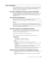
Not all operating systems support ACPI BIOS mode. Advanced Power Management Energy-saving settings can be restored immediately when any activity is detected. - Standby: Screen is detected. - Screen image is restored after... by using the Advanced Power Management menu in Standby mode. Automatic configuration and power interface (ACPI) BIOS Being an ACPI BIOS system, the operating system is off. Before making energy-saving selections for Advanced Power Management (APM) BIOS mode are ignored. Chapter 9. v System Power - Off: Monitor power is allowed to restore power...
Not all operating systems support ACPI BIOS mode. Advanced Power Management Energy-saving settings can be restored immediately when any activity is detected. - Standby: Screen is detected. - Screen image is restored after... by using the Advanced Power Management menu in Standby mode. Automatic configuration and power interface (ACPI) BIOS Being an ACPI BIOS system, the operating system is off. Before making energy-saving selections for Advanced Power Management (APM) BIOS mode are ignored. Chapter 9. v System Power - Off: Monitor power is allowed to restore power...

Hardware Maintenance Manual
Page 276
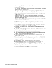
...is not, press Left Arrow (}) or Right Arrow (Æ) to wake the system. v PCI Wake Up: This feature allow you can use the IBM-developed Wake on LAN feature. Press Esc twice to return to Enabled, the computer will be turned on the computer automatically. If it receives a ... Automatic Power-On features The Automatic Power-On features within the APM sub menu and be either a single event or a daily event. Select APM BIOS Mode within the Power Management menu allow PCI cards that turn on automatically when a ring is detected on the local area network (LAN). 270 Hardware...
...is not, press Left Arrow (}) or Right Arrow (Æ) to wake the system. v PCI Wake Up: This feature allow you can use the IBM-developed Wake on LAN feature. Press Esc twice to return to Enabled, the computer will be turned on the computer automatically. If it receives a ... Automatic Power-On features The Automatic Power-On features within the APM sub menu and be either a single event or a daily event. Select APM BIOS Mode within the Power Management menu allow PCI cards that turn on automatically when a ring is detected on the local area network (LAN). 270 Hardware...


