User Guide
Page 5
...hard disk drive 21 Connecting an additional serial ATA hard disk drive 22 Security features 22 Integrated cable lock 23 Password protection 23 Changing the battery 23 Erasing a lost or forgotten password (clearing CMOS 24 Closing the cover and connecting the cables . . . 25 Chapter 2. Updating system programs 33 System program 33 Updating (flashing) BIOS from a diskette or CD-ROM 33 Updating (flashing) BIOS from your computer 8 Obtaining device drivers 9 Opening the cover 10 Locating components 11 Accessing system board components and drives . . 12 Identifying parts on password...
...hard disk drive 21 Connecting an additional serial ATA hard disk drive 22 Security features 22 Integrated cable lock 23 Password protection 23 Changing the battery 23 Erasing a lost or forgotten password (clearing CMOS 24 Closing the cover and connecting the cables . . . 25 Chapter 2. Updating system programs 33 System program 33 Updating (flashing) BIOS from a diskette or CD-ROM 33 Updating (flashing) BIOS from your computer 8 Obtaining device drivers 9 Opening the cover 10 Locating components 11 Accessing system board components and drives . . 12 Identifying parts on password...
User Guide
Page 14
Power supply statement Never remove the cover on a power supply or any component that has the following label attached. There are present inside these parts, contact a service technician. xii User Guide If you suspect a problem with one of these components. Hazardous voltage, current, and energy levels are no serviceable parts inside any part that has this label attached.
Power supply statement Never remove the cover on a power supply or any component that has the following label attached. There are present inside these parts, contact a service technician. xii User Guide If you suspect a problem with one of these components. Hazardous voltage, current, and energy levels are no serviceable parts inside any part that has this label attached.

User Guide
Page 15
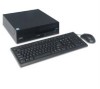
... installing your computer. The ThinkVantage™ Productivity Center program, on your needs change. Portions © IBM Corp. 2005. You can be upgraded as your desktop, provides a link to increase its capabilities. Your computer incorporates many of the latest advances in this publication. Instructions for installing external and internal options are included in computer technology and can find the following information: v CRU removal and installation instructions v Publications v Troubleshooting information v Parts information v Downloads...
... installing your computer. The ThinkVantage™ Productivity Center program, on your needs change. Portions © IBM Corp. 2005. You can be upgraded as your desktop, provides a link to increase its capabilities. Your computer incorporates many of the latest advances in this publication. Instructions for installing external and internal options are included in computer technology and can find the following information: v CRU removal and installation instructions v Publications v Troubleshooting information v Parts information v Downloads...
User Guide
Page 17
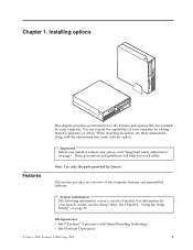
... section provides an overview of models. System information The following information covers a variety of the computer features and preinstalled software. For information for your specific model, use these instructions along with the instructions that come with HyperThreading Technology v Intel Pentium D processor © Lenovo 2005. When installing an option, use the Setup Utility. Important Before you work safely. See Chapter 2, "Using the Setup Utility," on page v. Installing options This chapter provides an...
... section provides an overview of models. System information The following information covers a variety of the computer features and preinstalled software. For information for your specific model, use these instructions along with the instructions that come with HyperThreading Technology v Intel Pentium D processor © Lenovo 2005. When installing an option, use the Setup Utility. Important Before you work safely. See Chapter 2, "Using the Setup Utility," on page v. Installing options This chapter provides an...

User Guide
Page 18
... Port (EPP) v Two 9-pin serial connectors v Eight USB connectors (two on front panel and six on rear panel) v Standard mouse connector v Standard keyboard connector v Ethernet connector v VGA monitor connector v Two audio connectors (line in and line out) on rear panel v Two audio connectors (microphone and headphone) on the rear panel v Mono internal speaker (some models) Connectivity v 10/100/1000 Mbps integrated Ethernet controller (some models) v Peripheral Component Interconnect (PCI) V.90 Data/Fax modem (some models) Video subsystem v An integrated graphics controller for a Video...
... Port (EPP) v Two 9-pin serial connectors v Eight USB connectors (two on front panel and six on rear panel) v Standard mouse connector v Standard keyboard connector v Ethernet connector v VGA monitor connector v Two audio connectors (line in and line out) on rear panel v Two audio connectors (microphone and headphone) on the rear panel v Mono internal speaker (some models) Connectivity v 10/100/1000 Mbps integrated Ethernet controller (some models) v Peripheral Component Interconnect (PCI) V.90 Data/Fax modem (some models) Video subsystem v An integrated graphics controller for a Video...

User Guide
Page 19
...v Startup sequence control v Startup without diskette drive, keyboard, or mouse v Unattended start mode v Diskette and hard disk I/O control v Serial and parallel port I/O control v Security profile by device Preinstalled software Your computer might be identified by model) v Linux® v Microsoft Windows 2000 1. Expansion v Three drive bays v One 32-bit PCI adapter connector v One PCI Express x1 adapter connector Power v 230 Watt power supply with manual voltage selection switch v Automatic 50/60 Hz input frequency switching v Advanced Power Management support v Advanced Configuration and...
...v Startup sequence control v Startup without diskette drive, keyboard, or mouse v Unattended start mode v Diskette and hard disk I/O control v Serial and parallel port I/O control v Security profile by device Preinstalled software Your computer might be identified by model) v Linux® v Microsoft Windows 2000 1. Expansion v Three drive bays v One 32-bit PCI adapter connector v One PCI Express x1 adapter connector Power v 230 Watt power supply with manual voltage selection switch v Automatic 50/60 Hz input frequency switching v Advanced Power Management support v Advanced Configuration and...

User Guide
Page 24
... locations of connectors on the rear of your computer. 1 Power cord connector 9 2 Cable lock latch 10 3 PCI Express x1 adapter connector 11 4 PCI adapter connector 12 5 Serial connectors (2) 13 6 Ethernet connector 14 7 USB connectors (2) 15 8 VGA monitor connector Parallel connector Audio line in connector Audio line out connector USB connectors (4) Standard keyboard connector Standard mouse connector Power supply diagnostic LEDs Note: Some connectors on the rear of your computer are color-coded to help you determine where to connect the cables on your computer. 8 User Guide
... locations of connectors on the rear of your computer. 1 Power cord connector 9 2 Cable lock latch 10 3 PCI Express x1 adapter connector 11 4 PCI adapter connector 12 5 Serial connectors (2) 13 6 Ethernet connector 14 7 USB connectors (2) 15 8 VGA monitor connector Parallel connector Audio line in connector Audio line out connector USB connectors (4) Standard keyboard connector Standard mouse connector Power supply diagnostic LEDs Note: Some connectors on the rear of your computer are color-coded to help you determine where to connect the cables on your computer. 8 User Guide

User Guide
Page 25
...operating systems that are provided in connector of the device and the audio line in README files with built-in amplifiers), headphones, multimedia keyboards, or the audio line in connector Used to attach a keyboard that uses a standard keyboard connector. Ethernet connector Used to attach an external modem, serial printer, or other pointing device that requires a Universal Serial Bus (USB) connection, such as powered stereo speakers (speakers with the device-driver files. USB connectors Used to attach a device that uses a standard mouse connector. Installation instructions...
...operating systems that are provided in connector of the device and the audio line in README files with built-in amplifiers), headphones, multimedia keyboards, or the audio line in connector Used to attach a keyboard that uses a standard keyboard connector. Ethernet connector Used to attach an external modem, serial printer, or other pointing device that requires a Universal Serial Bus (USB) connection, such as powered stereo speakers (speakers with the device-driver files. USB connectors Used to attach a device that uses a standard mouse connector. Installation instructions...

User Guide
Page 33
... panel installed. Installing options 17 The following illustration shows the locations of drives you can obtain a Universal Adapter Bracket, 5.25 to 3.5-inch) * 5.25-inch hard disk drive 3 Bay 3 - Drive specifications Your computer comes with the following factory-installed drives: v A 3.5-inch hard disk drive in bay 1 v An optical drive in bay 2 (some models) v A 3.5-inch diskette drive in .) 3.5-inch hard disk drive (preinstalled) 2 Bay 2 - Maximum height: 43.0 mm (1.7 in.) Optical drives, such as CD drive or DVD drive (preinstalled in some models) 3.5-inch hard disk drive...
... panel installed. Installing options 17 The following illustration shows the locations of drives you can obtain a Universal Adapter Bracket, 5.25 to 3.5-inch) * 5.25-inch hard disk drive 3 Bay 3 - Drive specifications Your computer comes with the following factory-installed drives: v A 3.5-inch hard disk drive in bay 1 v An optical drive in bay 2 (some models) v A 3.5-inch diskette drive in .) 3.5-inch hard disk drive (preinstalled) 2 Bay 2 - Maximum height: 43.0 mm (1.7 in.) Optical drives, such as CD drive or DVD drive (preinstalled in some models) 3.5-inch hard disk drive...

User Guide
Page 35
... a slave device. Note: A serial ATA hard disk drive does not need to the locked position. 13. Installing options 19 Slide the optical drive lock to the cable connections. 14. Installing a diskette drive in bay 3 To install a diskette drive in bay 3, do the following: 1. If you are installing any type of drive other than a serial ATA hard disk drive, make sure the drive that comes with your drive for master/slave jumper information. 10. Open the computer cover. Connect at "Connecting drives" on page...
... a slave device. Note: A serial ATA hard disk drive does not need to the locked position. 13. Installing options 19 Slide the optical drive lock to the cable connections. 14. Installing a diskette drive in bay 3 To install a diskette drive in bay 3, do the following: 1. If you are installing any type of drive other than a serial ATA hard disk drive, make sure the drive that comes with your drive for master/slave jumper information. 10. Open the computer cover. Connect at "Connecting drives" on page...

User Guide
Page 39
... type of your computer and is operated with many laptop computers. however, no charging or maintenance throughout its life; The cable lock attaches to a security slot at the rear of memory that maintains the date, time, and settings for normal use the Setup Utility program to set a password. Installing options 23 The cable lock also locks the buttons used with a key. This is displayed when you turn off the computer. Go to open the computer cover. The battery...
... type of your computer and is operated with many laptop computers. however, no charging or maintenance throughout its life; The cable lock attaches to a security slot at the rear of memory that maintains the date, time, and settings for normal use the Setup Utility program to set a password. Installing options 23 The cable lock also locks the buttons used with a key. This is displayed when you turn off the computer. Go to open the computer cover. The battery...

User Guide
Page 40
... computer. 2. Open the computer cover. See "Accessing system board components and drives" on page 10. 2. Install the new battery. 7. Note: When the computer is normal after battery replacement, an error message might be displayed. See Chapter 2, "Using the Setup Utility," on page 12. 3. For more information about replacing and disposing of the battery. See "Accessing system board components and drives" on page 27. Locate the Clear CMOS/Recovery jumper on page 13. 24 User Guide See "Identifying parts on the system board...
... computer. 2. Open the computer cover. See "Accessing system board components and drives" on page 10. 2. Install the new battery. 7. Note: When the computer is normal after battery replacement, an error message might be displayed. See Chapter 2, "Using the Setup Utility," on page 12. 3. For more information about replacing and disposing of the battery. See "Accessing system board components and drives" on page 27. Locate the Clear CMOS/Recovery jumper on page 13. 24 User Guide See "Identifying parts on the system board...
User Guide
Page 43
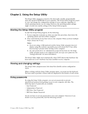
... configuration settings of your computer. When working with the Setup Utility program menu, you are using a USB keyboard and the Setup Utility program does not display using . The following types of your computer, regardless of each screen. Portions © IBM Corp. 2005. 27 Chapter 2. Using passwords By using the Setup Utility program, you can set any passwords, read -only memory (EEPROM) of passwords are displayed at the bottom of which operating system you must use your computer. However, the operating-system settings might start...
... configuration settings of your computer. When working with the Setup Utility program menu, you are using a USB keyboard and the Setup Utility program does not display using . The following types of your computer, regardless of each screen. Portions © IBM Corp. 2005. 27 Chapter 2. Using passwords By using the Setup Utility program, you can set any passwords, read -only memory (EEPROM) of passwords are displayed at the bottom of which operating system you must use your computer. However, the operating-system settings might start...

User Guide
Page 44
... error message. After you set an Administrator Password, a password prompt is set , the user is prompted to a local area network (LAN), the Wake on . When this password is displayed each time the computer is a good idea to type a valid password 28 User Guide Administrator Password Setting an Administrator Password deters unauthorized persons from changing configuration settings. v If your computer. v If you can type either password. If you must use a strong password that computer also supports the IDE Drive User password. If you type...
... error message. After you set an Administrator Password, a password prompt is set , the user is prompted to a local area network (LAN), the Wake on . When this password is displayed each time the computer is a good idea to type a valid password 28 User Guide Administrator Password Setting an Administrator Password deters unauthorized persons from changing configuration settings. v If your computer. v If you can type either password. If you must use a strong password that computer also supports the IDE Drive User password. If you type...

User Guide
Page 46
... IDE controller (such as hard disk drives or the CD-ROM drive) are using a USB keyboard and the Startup Device Menu does not display using this method, repeatedly press and release the F12 key rather than leaving it pressed when turning on the computer. 3. To set to Disable, the diskette drive cannot be displayed in the system configuration. Note: If you are disabled and will not be accessed. Select the desired startup device from any boot device. You...
... IDE controller (such as hard disk drives or the CD-ROM drive) are using a USB keyboard and the Startup Device Menu does not display using this method, repeatedly press and release the F12 key rather than leaving it pressed when turning on the computer. 3. To set to Disable, the diskette drive cannot be displayed in the system configuration. Note: If you are disabled and will not be accessed. Select the desired startup device from any boot device. You...
User Guide
Page 49
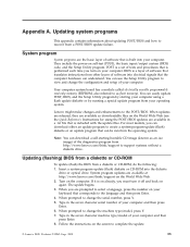
... machine type/model, press Y. 7. Updating (flashing) BIOS from a diskette or CD-ROM To update (flash) the BIOS from a POST/BIOS update failure. If it off and back on the screen to change the serial number, press Y. 5. You can easily update POST, BIOS, and the Setup Utility program by running a special update program from the operating system. Note: You can download either an update program to support systems without a diskette drive. Instructions for using a flash update diskette or by starting bootable CD image (known as downloadable...
... machine type/model, press Y. 7. Updating (flashing) BIOS from a diskette or CD-ROM To update (flash) the BIOS from a POST/BIOS update failure. If it off and back on the screen to change the serial number, press Y. 5. You can easily update POST, BIOS, and the Setup Utility program by running a special update program from the operating system. Note: You can download either an update program to support systems without a diskette drive. Instructions for using a flash update diskette or by starting bootable CD image (known as downloadable...

User Guide
Page 50
... the cover and connecting the cables" on the system board. Remove the diskette from the standard position (pins 1 and 2) to change. 1. From your machine type as printers, monitors, and external drives. 2. Turn off . Repeat steps 2 through 5. 13. Unplug all power cords from a POST/BIOS update failure If power to your computer is interrupted while POST/BIOS is subject to pins 2 and 3. 7. Locate the Clear CMOS/Recovery jumper on page 25. 9. d. See "Accessing system board components and drives" on the computer...
... the cover and connecting the cables" on the system board. Remove the diskette from the standard position (pins 1 and 2) to change. 1. From your machine type as printers, monitors, and external drives. 2. Turn off . Repeat steps 2 through 5. 13. Unplug all power cords from a POST/BIOS update failure If power to your computer is interrupted while POST/BIOS is subject to pins 2 and 3. 7. Locate the Clear CMOS/Recovery jumper on page 25. 9. d. See "Accessing system board components and drives" on the computer...
User Guide
Page 56
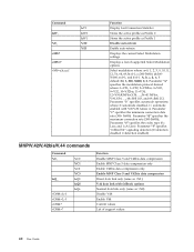
... the active profile as Profile 0 Stores the active profile as Profile 1 Disable auto-retrain Enable auto-retrain Displays the current Select Modulation settings Displays a list of support values 40 User Guide c=300-56000; e=0-1; Parameter "e" specifies the codec type (0= Law, and 1=A-Law). Parameter "b" specifies automode operations where: 0=automode disabled, 1= automode enabled with fallback options Normal data link only (same as \N1) V.42 data link with...
... the active profile as Profile 0 Stores the active profile as Profile 1 Disable auto-retrain Enable auto-retrain Displays the current Select Modulation settings Displays a list of support values 40 User Guide c=300-56000; e=0-1; Parameter "e" specifies the codec type (0= Law, and 1=A-Law). Parameter "b" specifies automode operations where: 0=automode disabled, 1= automode enabled with fallback options Normal data link only (same as \N1) V.42 data link with...

User Guide
Page 63
...updating (flashing) 33 Boot-block recovery 34 H hard disk drive recovery 29 hard disk drive security 28 I information resources xiii input/output (I/O) features 2 installing options adapters 15 internal drives 16 memory modules 14 security features 22 internal drives 2 C cables, connecting 25 changing startup device sequence 30 changing the battery 23 closing the cover 25 CMOS, clearing 24 components, internal 11 connecting drives 21 connector description 9 connectors front 7 rear 8 cover closing 25 opening 10 D device drivers 9 drives bays 17 internal 16 specifications 17 dual inline memory...
...updating (flashing) 33 Boot-block recovery 34 H hard disk drive recovery 29 hard disk drive security 28 I information resources xiii input/output (I/O) features 2 installing options adapters 15 internal drives 16 memory modules 14 security features 22 internal drives 2 C cables, connecting 25 changing startup device sequence 30 changing the battery 23 closing the cover 25 CMOS, clearing 24 components, internal 11 connecting drives 21 connector description 9 connectors front 7 rear 8 cover closing 25 opening 10 D device drivers 9 drives bays 17 internal 16 specifications 17 dual inline memory...

User Guide
Page 64
...28 passwords considerations 28 PCI adapter 15 physical specifications 5 power Advanced Configuration and Power Interface (ACPI) support 3 Advanced Power Management support 3 features 3 R recovering from a POST/BIOS update failure 34 resetting hard disk drive password 29 power-on password 29 riser card 15 S security cable lock 23 features 3 selecting startup device 30 temporary startup device 30 serial connector 9 Setup Utility 27 system board components, accessing 12 connectors 13 identifying parts 13 location 13 memory 4, 14 system management 2 system programs 33 U updating (flashing) BIOS 33...
...28 passwords considerations 28 PCI adapter 15 physical specifications 5 power Advanced Configuration and Power Interface (ACPI) support 3 Advanced Power Management support 3 features 3 R recovering from a POST/BIOS update failure 34 resetting hard disk drive password 29 power-on password 29 riser card 15 S security cable lock 23 features 3 selecting startup device 30 temporary startup device 30 serial connector 9 Setup Utility 27 system board components, accessing 12 connectors 13 identifying parts 13 location 13 memory 4, 14 system management 2 system programs 33 U updating (flashing) BIOS 33...


