Information Manual
Page 5
... IBM Corp. 1996, 1997 iii Contents Preface vii Manual Style vii Related Publications viii Chapter 1. System Compatibility 26 Hardware Compatibility 26 Software Compatibility 29 Appendix A. Connector Pin Assignments 30 System Memory Connectors 30 EIDE Connectors 33 Diskette Drive Connector 34 Serial Port Connector 35 Parallel Port Connector 35 Keyboard and Mouse Port Connectors 36 USB Connector 37 Infrared Port Connector 37 ISA Connectors 38 PCI Connector 40 Appendix B. Adapters and Internal Drives 17 Graphics Adapters 17 SCSI Adapter 18 Internal Drives...
... IBM Corp. 1996, 1997 iii Contents Preface vii Manual Style vii Related Publications viii Chapter 1. System Compatibility 26 Hardware Compatibility 26 Software Compatibility 29 Appendix A. Connector Pin Assignments 30 System Memory Connectors 30 EIDE Connectors 33 Diskette Drive Connector 34 Serial Port Connector 35 Parallel Port Connector 35 Keyboard and Mouse Port Connectors 36 USB Connector 37 Infrared Port Connector 37 ISA Connectors 38 PCI Connector 40 Appendix B. Adapters and Internal Drives 17 Graphics Adapters 17 SCSI Adapter 18 Internal Drives...

Information Manual
Page 7
Serial Port Assignments 9 5. System Power Connection 15 10. Wake on Modem Ring Connections 15 11. Drives with Optical Media 19 20. Keyboard Port 21 24. PCI-Bus Adapters (Per Slot 21 27. Internal Devices (DASD 22 28. Electrical 25 37. 5.25-Inch Diskette Drive Reading, Writing, and Formatting Capabilities 28 38. 3.5-Inch Diskette Drive Reading, Writing, and Formatting Capabilities 28 39. 168-Pin Assignments for the System Memory Connector 30 40. 40...
Serial Port Assignments 9 5. System Power Connection 15 10. Wake on Modem Ring Connections 15 11. Drives with Optical Media 19 20. Keyboard Port 21 24. PCI-Bus Adapters (Per Slot 21 27. Internal Devices (DASD 22 28. Electrical 25 37. 5.25-Inch Diskette Drive Reading, Writing, and Formatting Capabilities 28 38. 3.5-Inch Diskette Drive Reading, Writing, and Formatting Capabilities 28 39. 168-Pin Assignments for the System Memory Connector 30 40. 40...
Information Manual
Page 9
... be preserved. Preface This Technical Information Manual provides information for developers who want to provide hardware and software products to operate with this IBM computer and provides a more in-depth view of how this computer works. When expressing storage capacity, MB equals 1 000 KB (1 024 000). Users of the letter "h" indicates a hexadecimal number. The use of this manual, some signals are abbreviated...
... be preserved. Preface This Technical Information Manual provides information for developers who want to provide hardware and software products to operate with this IBM computer and provides a more in-depth view of how this computer works. When expressing storage capacity, MB equals 1 000 KB (1 024 000). Users of the letter "h" indicates a hexadecimal number. The use of this manual, some signals are abbreviated...
Information Manual
Page 10
... publication includes general information about using computers and detailed information about configuring, operating, and maintaining the PC 365. Related Publications In addition to this publication includes troubleshooting information for the PC 365. PC 365 Microprocessor Upgrade Installation Instructions This publication contains information about compatible hardware and software for related video problems. Adaptec SCSI Support Package This documentation, which is available at http://www.pc.ibm.com/cdt. In other countries...
... publication includes general information about using computers and detailed information about configuring, operating, and maintaining the PC 365. Related Publications In addition to this publication includes troubleshooting information for the PC 365. PC 365 Microprocessor Upgrade Installation Instructions This publication contains information about compatible hardware and software for related video problems. Adaptec SCSI Support Package This documentation, which is available at http://www.pc.ibm.com/cdt. In other countries...

Information Manual
Page 11
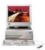
... support Support for future growth. S3 Trio64V+ SVGA Graphics Adapter or Matrox MGA Millennium Graphics Adapter Riser card - 3 shared ISA/PCI connectors, 2 dedicated ISA connectors or 3 shared ISA/PCI connectors, 2 dedicated PCI connectors Drive with the graphics adapter One universal serial bus port One infrared port capable of system memory Enhanced IDE (EIDE) interface Hard disk drive (EIDE or Fast/Wide SCSI) One 3.5-inch, 1.44 MB diskette drive One high-speed serial port One high-speed parallel port One monitor port provided with optical...
... support Support for future growth. S3 Trio64V+ SVGA Graphics Adapter or Matrox MGA Millennium Graphics Adapter Riser card - 3 shared ISA/PCI connectors, 2 dedicated ISA connectors or 3 shared ISA/PCI connectors, 2 dedicated PCI connectors Drive with the graphics adapter One universal serial bus port One infrared port capable of system memory Enhanced IDE (EIDE) interface Hard disk drive (EIDE or Fast/Wide SCSI) One 3.5-inch, 1.44 MB diskette drive One high-speed serial port One high-speed parallel port One monitor port provided with optical...
Information Manual
Page 12
...Software Features The PC 365 supports a variety of a text message displays on self-test (POST) software. The RTC CD-ROM has applications and device driver support for a listing of a POST error code, see "POST Error Codes" on self-test (POST) Configuration/Setup Utility program Advanced Power Management (APM) Flash update utility program Diagnostic programs BIOS The computer system uses the IBM SurePath BIOS. System software includes: Basic input/output system (BIOS) Plug and Play Power-on page 48. 2 Technical Information Manual Chapter 1. For a description of supported operating...
...Software Features The PC 365 supports a variety of a text message displays on self-test (POST) software. The RTC CD-ROM has applications and device driver support for a listing of a POST error code, see "POST Error Codes" on self-test (POST) Configuration/Setup Utility program Advanced Power Management (APM) Flash update utility program Diagnostic programs BIOS The computer system uses the IBM SurePath BIOS. System software includes: Basic input/output system (BIOS) Plug and Play Power-on page 48. 2 Technical Information Manual Chapter 1. For a description of supported operating...

Information Manual
Page 13
... devices, I/O ports, date and time, system security, start options, advanced setup, ISA legacy resources, and power management. More information on a 3.5-inch diskette. For more information on APM, see Using Your Personal Computer. 2 APM does not support small computer system interface (SCSI) hard disk drives. Diagnostic Programs Two diagnostic products are not in Using Your Personal Computer. Chapter 1. System Overview 3 When enabled, APM initiates reduced-power modes for the monitor...
... devices, I/O ports, date and time, system security, start options, advanced setup, ISA legacy resources, and power management. More information on a 3.5-inch diskette. For more information on APM, see Using Your Personal Computer. 2 APM does not support small computer system interface (SCSI) hard disk drives. Diagnostic Programs Two diagnostic products are not in Using Your Personal Computer. Chapter 1. System Overview 3 When enabled, APM initiates reduced-power modes for the monitor...
Information Manual
Page 14
... installation. 4 © Copyright IBM Corp. 1996, 1997 The dual processing configuration is the Intel P6, called the Pentium Pro. To locate these connectors, see "Switches" on page 14. The upgrade kit includes a Pentium Pro microprocessor, a fan-sink assembly, a voltage-regulator module, and instructions for the PC 365 is provided for 32-bit software Internal L2 cache - 4-way set associative - To view an illustration of the system board...
... installation. 4 © Copyright IBM Corp. 1996, 1997 The dual processing configuration is the Intel P6, called the Pentium Pro. To locate these connectors, see "Switches" on page 14. The upgrade kit includes a Pentium Pro microprocessor, a fan-sink assembly, a voltage-regulator module, and instructions for the PC 365 is provided for 32-bit software Internal L2 cache - 4-way set associative - To view an illustration of the system board...

Information Manual
Page 15
... integrated drive electronics (EIDE) interface, and a universal serial bus (USB) port. The DIMM connectors are provided on page 6.) Also, this chip set controls the system memory interface. To enable error-correcting code, all four connectors). This chip set . The PC 365 also uses the PIIX3 chip. System Memory Four dual inline memory module (DIMM) connectors are powered by DIMMs include: 168-pin, unbuffered +3 V modules only. Gold-lead tabs only. 60 nanosecond access speeds only...
... integrated drive electronics (EIDE) interface, and a universal serial bus (USB) port. The DIMM connectors are provided on page 6.) Also, this chip set controls the system memory interface. To enable error-correcting code, all four connectors). This chip set . The PC 365 also uses the PIIX3 chip. System Memory Four dual inline memory module (DIMM) connectors are powered by DIMMs include: 168-pin, unbuffered +3 V modules only. Gold-lead tabs only. 60 nanosecond access speeds only...

Information Manual
Page 17
... resources used by switches or jumpers on page 19. The IDE devices receive their power through a ribbon cable that complies with AT Attachment Interface with the EIDE interface. Two 40-pin connectors are subject to one device is designated as the secondary, or subordinate, device. A bootable hard disk drive can be installed in the computer, see "EIDE Connectors" on the system board. this allows concurrent operations on...
... resources used by switches or jumpers on page 19. The IDE devices receive their power through a ribbon cable that complies with AT Attachment Interface with the EIDE interface. Two 40-pin connectors are subject to one device is designated as the secondary, or subordinate, device. A bootable hard disk drive can be installed in the computer, see "EIDE Connectors" on the system board. this allows concurrent operations on...

Information Manual
Page 18
... USB is started, the resource assignments are subject to change during the power-on page 37. 8 Technical Information Manual Table 3. Features provided by the USB interface. The USB connector uses Plug and Play technology for specific devices Wide range of packet sizes Limited power to hub Guaranteed bandwidth and low latencies appropriate for installed devices. Chapter 2. At the rear of 255 peripheral devices. A USB-enabled device can be attached to the connector...
... USB is started, the resource assignments are subject to change during the power-on page 37. 8 Technical Information Manual Table 3. Features provided by the USB interface. The USB connector uses Plug and Play technology for specific devices Wide range of packet sizes Limited power to hub Guaranteed bandwidth and low latencies appropriate for installed devices. Chapter 2. At the rear of 255 peripheral devices. A USB-enabled device can be attached to the connector...
Information Manual
Page 20
...-Remote mode The system board has one 9-pin connector for the parallel port used in configuration. Table 5. System Board Features Infrared Port Two UART serial ports are selected through the Configuration/Setup Utility program with IEEE 1284. One of operation are integrated into the system board. The modes of these ports is integrated into the system board. The infrared port is capable of the same four assignments as the serial port. When an optional...
...-Remote mode The system board has one 9-pin connector for the parallel port used in configuration. Table 5. System Board Features Infrared Port Two UART serial ports are selected through the Configuration/Setup Utility program with IEEE 1284. One of operation are integrated into the system board. The modes of these ports is integrated into the system board. The infrared port is capable of the same four assignments as the serial port. When an optional...

Information Manual
Page 25
... Normal Clear CMOS Chapter 2. System Power Connection Pin 1 2 Description Auxiliary (+5 V dc) Power switch input Table 10. J8 - Wake on LAN Connection Pin 1 2 Description Ground External Wake on Modem/Ring Table 11. J3 - J15 - Chapter 2. Wake on Modem Ring Connections Pin Description 1 Ground 2 Wake on LAN/Ring Table 12. System Board Features Connections and the CMOS-Clear Jumper Connections and jumpers on page 14. Table 9. To locate these components, see "System Board" on the system board allow custom configurations. System Board...
... Normal Clear CMOS Chapter 2. System Power Connection Pin 1 2 Description Auxiliary (+5 V dc) Power switch input Table 10. J8 - Wake on LAN Connection Pin 1 2 Description Ground External Wake on Modem/Ring Table 11. J3 - J15 - Chapter 2. Wake on Modem Ring Connections Pin Description 1 Ground 2 Wake on LAN/Ring Table 12. System Board Features Connections and the CMOS-Clear Jumper Connections and jumpers on page 14. Table 9. To locate these components, see "System Board" on the system board allow custom configurations. System Board...
Information Manual
Page 27
... be disabled in the Configuration/Setup Utility program) DMA None Note: When the computer is not supported. Chapter 3. Instructions for installing device drivers for each adapter provides a 15-pin monitor connector (the Matrox MGA Millennium Graphics Adapter also provides a multimedia connector for PCI or an IDE expansion adapter is started, the resource assignments are compliant with a graphics adapter and, in S3 Trio64V+ SVGA Device Driver Installation Instructions and Matrox MGA Millennium Graphics Adapter Software Installation Guide. S3 Trio64V+ SVGA Graphics Adapter If...
... be disabled in the Configuration/Setup Utility program) DMA None Note: When the computer is not supported. Chapter 3. Instructions for installing device drivers for each adapter provides a 15-pin monitor connector (the Matrox MGA Millennium Graphics Adapter also provides a multimedia connector for PCI or an IDE expansion adapter is started, the resource assignments are compliant with a graphics adapter and, in S3 Trio64V+ SVGA Device Driver Installation Instructions and Matrox MGA Millennium Graphics Adapter Software Installation Guide. S3 Trio64V+ SVGA Graphics Adapter If...

Information Manual
Page 28
... PC 365 has five drive bays. SCSI Adapter Some models come with the standard PD/CD-ROM drive installed. Note: A maximum of Windows RAM (WRAM), upgradable to internal SCSI devices. System Resource Assignments for attaching the SCSI adapter to 8 MB One 15-pin monitor connector One multimedia connector for attaching video devices Support for all VGA modes VESA 2.0 compliance for SVGA modes Video POST/BIOS code The following major features are provided: 4 MB of three internal SCSI hard disk drives are installed. Multiple internal and external drives...
... PC 365 has five drive bays. SCSI Adapter Some models come with the standard PD/CD-ROM drive installed. Note: A maximum of Windows RAM (WRAM), upgradable to internal SCSI devices. System Resource Assignments for attaching the SCSI adapter to 8 MB One 15-pin monitor connector One multimedia connector for attaching video devices Support for all VGA modes VESA 2.0 compliance for SVGA modes Video POST/BIOS code The following major features are provided: 4 MB of three internal SCSI hard disk drives are installed. Multiple internal and external drives...
Information Manual
Page 29
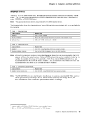
... Maximum installed Optional drives Number/Size One 3.5-inch, 1.44 MB Three (the cable provided allows for attaching internal drives. When used as a standard CD-ROM reader or as a backup and storage device, the PD/CD-ROM drive uses a rewritable optical disk encased in the computer. The PC 365 comes standard with an EIDE or Fast/Wide SCSI hard disk drive, a diskette drive, and a CD-ROM or a PD/CD-ROM drive.3 Note: The appropriate device drivers are installed. Adapters and Internal Drives 19...
... Maximum installed Optional drives Number/Size One 3.5-inch, 1.44 MB Three (the cable provided allows for attaching internal drives. When used as a standard CD-ROM reader or as a backup and storage device, the PD/CD-ROM drive uses a rewritable optical disk encased in the computer. The PC 365 comes standard with an EIDE or Fast/Wide SCSI hard disk drive, a diskette drive, and a CD-ROM or a PD/CD-ROM drive.3 Note: The appropriate device drivers are installed. Adapters and Internal Drives 19...

Information Manual
Page 36
... diskette drive controllers The Intel 8042 keyboard controller at addresses 0060h and 0064h All video standards using VGA, EGA, CGA, MDA, and Hercules modes The parallel printer ports (Parallel 1, Parallel 2, and Parallel 3) in compatibility mode Use the following interfaces: The Intel 8259 interrupt controllers (edge-triggered mode) The National Semiconductor NS16450 and NS16550A serial communication controllers The Motorola MC146818 Time of compatible hardware and software options. In most cases...
... diskette drive controllers The Intel 8042 keyboard controller at addresses 0060h and 0064h All video standards using VGA, EGA, CGA, MDA, and Hercules modes The parallel printer ports (Parallel 1, Parallel 2, and Parallel 3) in compatibility mode Use the following interfaces: The Intel 8259 interrupt controllers (edge-triggered mode) The National Semiconductor NS16450 and NS16550A serial communication controllers The Motorola MC146818 Time of compatible hardware and software options. In most cases...
Information Manual
Page 58
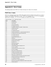
... error 113 I/O channel check error 114 External ROM checksum error 115 DMA error 116 System board port read/write error 120 Microprocessor test error 121 Hardware error 151 Real time clock failure 161 Bad CMOS Battery 162 CMOS RAM checksum/configuration error 163 Clock not updating 164 CMOS RAM memory size does not match 167 Clock not updating 175 Riser card or system board error 176 System cover has been removed 177 Corrupted administrator password 178 Riser card or system board error 183 Administrator password...
... error 113 I/O channel check error 114 External ROM checksum error 115 DMA error 116 System board port read/write error 120 Microprocessor test error 121 Hardware error 151 Real time clock failure 161 Bad CMOS Battery 162 CMOS RAM checksum/configuration error 163 Clock not updating 164 CMOS RAM memory size does not match 167 Clock not updating 175 Riser card or system board error 176 System cover has been removed 177 Corrupted administrator password 178 Riser card or system board error 183 Administrator password...

Information Manual
Page 59
...221 ROM to RAM remapping error 225 Unsupported memory type installed or memory pair mismatch 301 Keyboard error 302 Keyboard error 303 Keyboard to system board interface error 304 Keyboard clock high 305 No keyboard +5 V dc 601 Diskette drive or controller error 602 Diskette IPL boot record not valid 604 Unsupported diskette drive installed 605 POST cannot unlock diskette drive 662 Diskette drive configuration error 762 Math coprocessor configuration error 11xx Serial port error (xx = serial port number) 1762 Hard disk configuration error 1780 Hard disk 0 failed...
...221 ROM to RAM remapping error 225 Unsupported memory type installed or memory pair mismatch 301 Keyboard error 302 Keyboard error 303 Keyboard to system board interface error 304 Keyboard clock high 305 No keyboard +5 V dc 601 Diskette drive or controller error 602 Diskette IPL boot record not valid 604 Unsupported diskette drive installed 605 POST cannot unlock diskette drive 662 Diskette drive configuration error 762 Math coprocessor configuration error 11xx Serial port error (xx = serial port number) 1762 Hard disk configuration error 1780 Hard disk 0 failed...
Information Manual
Page 64
... O operating systems 2 outputs, power supply 21 overvoltage fault 22 P parallel port 10 PCI bus 6, 13 connectors 13 PCI-to-ISA bridge 6 Pentium Pro microprocessor 4 pin descriptions connections 15 diskette drive connector 34 EIDE connectors 33 infrared connector 37 ISA connector 38 keyboard/mouse connectors 36 parallel port connector 35 PCI connector 40 serial port connector 35 system memory 30 USB connector 37 Plug and Play 2 polling mechanism 29 port GPIO 11 keyboard/mouse 10, 11 parallel 10 serial 9 POST 2 POST error codes 48 power APM modes 3 cable...
... O operating systems 2 outputs, power supply 21 overvoltage fault 22 P parallel port 10 PCI bus 6, 13 connectors 13 PCI-to-ISA bridge 6 Pentium Pro microprocessor 4 pin descriptions connections 15 diskette drive connector 34 EIDE connectors 33 infrared connector 37 ISA connector 38 keyboard/mouse connectors 36 parallel port connector 35 PCI connector 40 serial port connector 35 system memory 30 USB connector 37 Plug and Play 2 polling mechanism 29 port GPIO 11 keyboard/mouse 10, 11 parallel 10 serial 9 POST 2 POST error codes 48 power APM modes 3 cable...


