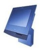
Service Guide
Page 6
... card - removing and replacing 74 Rear connector panel (tailgate) - removing and replacing 45 Hinge cover - removing and replacing 78 Integrated customer display - removing and replacing 81 Mounting options - removing and replacing 64 System board - removing and replacing 40 Side covers - removing and ...Using the Service Diskette (for the 5x3 models 30 Using the IBM Diagnostics for Peripherals (for the 5x3 models 31 Using the IBM Diagnostics for POS System Units and Peripherals (for the SurePOS 500 Models 5x3 and 544/564 33 Handling static-sensitive devices 34 ...
... card - removing and replacing 74 Rear connector panel (tailgate) - removing and replacing 45 Hinge cover - removing and replacing 78 Integrated customer display - removing and replacing 81 Mounting options - removing and replacing 64 System board - removing and replacing 40 Side covers - removing and ...Using the Service Diskette (for the 5x3 models 30 Using the IBM Diagnostics for Peripherals (for the 5x3 models 31 Using the IBM Diagnostics for POS System Units and Peripherals (for the SurePOS 500 Models 5x3 and 544/564 33 Handling static-sensitive devices 34 ...

Service Guide
Page 7
... SurePoint Solution Model 4FT, 4FD, 2GN, 5GN, or 2GB removal on keyboard integration tray 130 Mounting the display tablet on a remote display stand 132 Chapter 5. Assembly 6: Cash drawer non-keyboard integration tray and filler panels Assembly 7: Countertop and ...altitude limits 187 Appendix D. SurePOS 500 Models 5x3 and 544/564 tips 189 Contents v Compact ANPOS Keyboard 135 Keyboard/pointer symptoms 135 CANPOS Keyboard components - removal 122 4610 SureMark printer - removing and replacing 113 Distributed customer display - disassembling 118 IBM 4610 SureMark printers - August...
... SurePoint Solution Model 4FT, 4FD, 2GN, 5GN, or 2GB removal on keyboard integration tray 130 Mounting the display tablet on a remote display stand 132 Chapter 5. Assembly 6: Cash drawer non-keyboard integration tray and filler panels Assembly 7: Countertop and ...altitude limits 187 Appendix D. SurePOS 500 Models 5x3 and 544/564 tips 189 Contents v Compact ANPOS Keyboard 135 Keyboard/pointer symptoms 135 CANPOS Keyboard components - removal 122 4610 SureMark printer - removing and replacing 113 Distributed customer display - disassembling 118 IBM 4610 SureMark printers - August...
Service Guide
Page 10
.... Lock accessories 116 94. Attaching the 4610 SureMark printer mounting plate for the SurePOS 500 Models 5x3 and 544/564 88 65. Removing the coin-roll cutter 112 89. Cash-drawer latch and sensor assembly 115 93. Remove the distributed customer display from the keyboard integration tray . . . . . 131 viii Removing and replacing the compact...
.... Lock accessories 116 94. Attaching the 4610 SureMark printer mounting plate for the SurePOS 500 Models 5x3 and 544/564 88 65. Removing the coin-roll cutter 112 89. Cash-drawer latch and sensor assembly 115 93. Remove the distributed customer display from the keyboard integration tray . . . . . 131 viii Removing and replacing the compact...
Service Guide
Page 13
...135 12. Assignments for 15-pin serial connector 183 31. Assignment of parallel-connector pins 183 32. SurePOS 500 Models 5x3 and 544/564 task information 25 7. MSR connector-pin assignments 179 23. Keyboard and...IBM Corp. 2004, 2006 xi August 3, 2006 Tables | 1. Assignment of cash drawer connector pins 186 36. Assignment of integrated customer-display connector pins 186 37. Keyboard part numbers 137 13. USB port connector-pin assignments 180 24. Ethernet connector-pin assignments 184 34. Using the touch screen 17 6. Symptoms and actions 27 8. SurePOS 500...
...135 12. Assignments for 15-pin serial connector 183 31. Assignment of parallel-connector pins 183 32. SurePOS 500 Models 5x3 and 544/564 task information 25 7. MSR connector-pin assignments 179 23. Keyboard and...IBM Corp. 2004, 2006 xi August 3, 2006 Tables | 1. Assignment of cash drawer connector pins 186 36. Assignment of integrated customer-display connector pins 186 37. Keyboard part numbers 137 13. USB port connector-pin assignments 180 24. Ethernet connector-pin assignments 184 34. Using the touch screen 17 6. Symptoms and actions 27 8. SurePOS 500...
Service Guide
Page 59
... and replacing 48 Display tablet cable - removing and replacing 57 Cable tie bar - removing and replacing 69 Processor module - removing and replacing 82 Free-standing SurePOS 500 Models 5x3 and ... 74 Rear connector panel (tailgate) - removing 74 PC card - removing and replacing 78 Integrated customer display - removing and replacing 84 Countertop non-keyboard integration tray systems - August 3, 2006 Chapter 4. ... Removing and replacing FRUs for countertop and cash drawer 91 © Copyright IBM Corp. 2004, 2006 33 removing and replacing 37 Rear cover - removing ...
... and replacing 48 Display tablet cable - removing and replacing 57 Cable tie bar - removing and replacing 69 Processor module - removing and replacing 82 Free-standing SurePOS 500 Models 5x3 and ... 74 Rear connector panel (tailgate) - removing 74 PC card - removing and replacing 78 Integrated customer display - removing and replacing 84 Countertop non-keyboard integration tray systems - August 3, 2006 Chapter 4. ... Removing and replacing FRUs for countertop and cash drawer 91 © Copyright IBM Corp. 2004, 2006 33 removing and replacing 37 Rear cover - removing ...

Service Guide
Page 60
...the latch and sensor assembly 115 Removing and replacing the keylock insert 116 Removing and replacing the blank lock insert 116 Distributed customer display - removing and replacing 105 Removing and replacing a full-size drawer 105 Removing and replacing a full-size slide assembly 106...FRUs - disassembling 118 IBM 4610 SureMark printers - See Figure 10 on page xiii. 2. Removing and replacing August 3, 2006 Compact-size keyboard integration tray mounting for features that are not available on all SurePOS 500 Models 5x3 and 544/564 models (4840), although some procedures ...
...the latch and sensor assembly 115 Removing and replacing the keylock insert 116 Removing and replacing the blank lock insert 116 Distributed customer display - removing and replacing 105 Removing and replacing a full-size drawer 105 Removing and replacing a full-size slide assembly 106...FRUs - disassembling 118 IBM 4610 SureMark printers - See Figure 10 on page xiii. 2. Removing and replacing August 3, 2006 Compact-size keyboard integration tray mounting for features that are not available on all SurePOS 500 Models 5x3 and 544/564 models (4840), although some procedures ...
Service Guide
Page 86
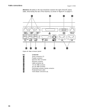
Connector A Serial connectors (3) B Parallel connector C External video connector D Ethernet connector E USB connectors (2) F 12-volt USB connector G 24-volt USB connector H Distributed customer display connector I J Figure 40. A B C D E F G H I Keyboard/mouse cable J Cash drawer connectors (2) 60 Cable connections August 3, 2006 Attention: All cables in the rear should be routed to the right of the AC power cable, when facing the rear of the machine, as shown in Figure 41 on page 61. Rear connector panel Ref.
Connector A Serial connectors (3) B Parallel connector C External video connector D Ethernet connector E USB connectors (2) F 12-volt USB connector G 24-volt USB connector H Distributed customer display connector I J Figure 40. A B C D E F G H I Keyboard/mouse cable J Cash drawer connectors (2) 60 Cable connections August 3, 2006 Attention: All cables in the rear should be routed to the right of the AC power cable, when facing the rear of the machine, as shown in Figure 41 on page 61. Rear connector panel Ref.
Service Guide
Page 103
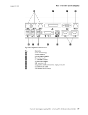
Tailgate connector locations Ref. Connector A Serial connectors (3) B Parallel connector C External video connector D Ethernet connector E 12-volt USB connector F 24-volt USB connector G USB connectors (2) H Integrated or distributed customer display connector I J Figure 54. Removing and replacing FRUs for the SurePOS 500 Models 5x3 and 544/564 77 August 3, 2006 A Rear connector panel (tailgate) B C D E F G H I Keyboard/mouse cable J Cash drawer connectors (2) Chapter 4.
Tailgate connector locations Ref. Connector A Serial connectors (3) B Parallel connector C External video connector D Ethernet connector E 12-volt USB connector F 24-volt USB connector G USB connectors (2) H Integrated or distributed customer display connector I J Figure 54. Removing and replacing FRUs for the SurePOS 500 Models 5x3 and 544/564 77 August 3, 2006 A Rear connector panel (tailgate) B C D E F G H I Keyboard/mouse cable J Cash drawer connectors (2) Chapter 4.
Service Guide
Page 105
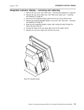
... "Top cover - Removing and replacing FRUs for the SurePOS 500 Models 5x3 and 544/564 79 removing and replacing 1. Remove the rear inner metal cover. Figure 56. Integrated display Chapter 4. Disconnect the integrated display cable from the rear of the system board. 7. Snap... the new integrated display in place, after routing the cable through the hole in the top of the unit. 6. August 3, 2006 Integrated customer display Integrated customer display - See "Rear ...
... "Top cover - Removing and replacing FRUs for the SurePOS 500 Models 5x3 and 544/564 79 removing and replacing 1. Remove the rear inner metal cover. Figure 56. Integrated display Chapter 4. Disconnect the integrated display cable from the rear of the system board. 7. Snap... the new integrated display in place, after routing the cable through the hole in the top of the unit. 6. August 3, 2006 Integrated customer display Integrated customer display - See "Rear ...
Service Guide
Page 114
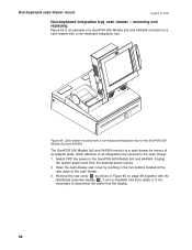
... Figure 64 is not necessary to a cash drawer by pushing in Figure 65 on a cash drawer with the distributed customer display D , if one is installed) and set it aside. It is an example of a SurePOS 500 Models 5x3 and 544/564 mounted on page 89 (together with a non-keyboard integration tray. Switch OFF the...
... Figure 64 is not necessary to a cash drawer by pushing in Figure 65 on a cash drawer with the distributed customer display D , if one is installed) and set it aside. It is an example of a SurePOS 500 Models 5x3 and 544/564 mounted on page 89 (together with a non-keyboard integration tray. Switch OFF the...
Service Guide
Page 115
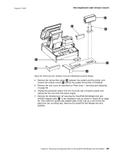
Removing rear modesty cover and distributed customer display 4. Remove the narrow filler panel A between the system and the printer, and remove the vertical covers B behind the system and printer (if installed). 5. removing and ... D B F E C B A Figure 65. Remove the rear cover as shown in Figure 66 on page 38. 6. Chapter 4. Removing and replacing FRUs for the SurePOS 500 Models 5x3 and 544/564 89 Remove the SurePOS 500 Models 5x3 and 544/564. Unplug the peripheral cables from the front and rear connector panels and unplug the line cord...
Removing rear modesty cover and distributed customer display 4. Remove the narrow filler panel A between the system and the printer, and remove the vertical covers B behind the system and printer (if installed). 5. removing and ... D B F E C B A Figure 65. Remove the rear cover as shown in Figure 66 on page 38. 6. Chapter 4. Removing and replacing FRUs for the SurePOS 500 Models 5x3 and 544/564 89 Remove the SurePOS 500 Models 5x3 and 544/564. Unplug the peripheral cables from the front and rear connector panels and unplug the line cord...
Service Guide
Page 118
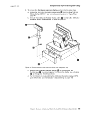
... on the full-size keyboard-integration tray: 1. Prepare the SurePOS 500 Models 5x3 and 544/564 for disassembly by removing the two thumbscrews C from the external power source. Switch OFF the power to the SurePOS 500 Models 5x3 and 544/564. d. To remove the distributed customer display, perform the following steps: 92 Lift up through slot...
... on the full-size keyboard-integration tray: 1. Prepare the SurePOS 500 Models 5x3 and 544/564 for disassembly by removing the two thumbscrews C from the external power source. Switch OFF the power to the SurePOS 500 Models 5x3 and 544/564. d. To remove the distributed customer display, perform the following steps: 92 Lift up through slot...
Service Guide
Page 124
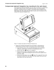
... tray August 3, 2006 Compact-size keyboard integration tray mounting for the devices that are being removed: a. A printer can accommodate a keyboard, a distributed customer display, or a SurePoint Solution (Machine Type: 4820, Models 4FT, 4FD, 2GN, 5GN, and 2GB). b. Remove filler panel E Figure 75 on page... on page 99. The compact cash drawer can not be mounted on the compact-size keyboard-integration tray. d. Prepare the SurePOS 500 Models 5x3 and 544/564 for disassembly by performing the necessary steps for the cash drawer The compact-size keyboard-integration tray ...
... tray August 3, 2006 Compact-size keyboard integration tray mounting for the devices that are being removed: a. A printer can accommodate a keyboard, a distributed customer display, or a SurePoint Solution (Machine Type: 4820, Models 4FT, 4FD, 2GN, 5GN, and 2GB). b. Remove filler panel E Figure 75 on page... on page 99. The compact cash drawer can not be mounted on the compact-size keyboard-integration tray. d. Prepare the SurePOS 500 Models 5x3 and 544/564 for disassembly by performing the necessary steps for the cash drawer The compact-size keyboard-integration tray ...
Service Guide
Page 125
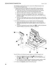
... removing the two thumbscrews C from integration tray c. Lift up through the mounting post slot. Unroute the distributed character display cable F to enable the distributed character display to "Distributed customer display - Unplug the distributed character display cable F from the SurePOS 500 Models 5x3 and 544/564 rear connector panel, as show in Figure 75. To remove the distributed...
... removing the two thumbscrews C from integration tray c. Lift up through the mounting post slot. Unroute the distributed character display cable F to enable the distributed character display to "Distributed customer display - Unplug the distributed character display cable F from the SurePOS 500 Models 5x3 and 544/564 rear connector panel, as show in Figure 75. To remove the distributed...
Service Guide
Page 144
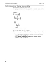
... non-keyboard integration tray or keyboard integration tray procedure to complete the installation of the distributed customer display: v For a non-keyboard integration tray installation of a distributed customer display, go to Step 4 on page 120. 118 disassembling To disassemble a distributed customer display: 1. v For a keyboard integration tray installation of the yoke. Gently spread the arms of the yoke...
... non-keyboard integration tray or keyboard integration tray procedure to complete the installation of the distributed customer display: v For a non-keyboard integration tray installation of a distributed customer display, go to Step 4 on page 120. 118 disassembling To disassemble a distributed customer display: 1. v For a keyboard integration tray installation of the yoke. Gently spread the arms of the yoke...

Service Guide
Page 145
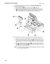
... customer display to the system unit rear connector panel. Remove one of the tray. To install a distributed customer display D on page 60. h. August 3, 2006 Distributed customer display 4. D B F E C B A Figure 95. Route the character display ...cable to the cash drawer, with 2 thumbscrews F and snap the entire unit into the 15-pin serial connector, as shown in the modesty panel. f. Reinstall filler panels B first then install A in Figure 40 on a non-keyboard integration tray, perform the following steps: a. d. Removing and replacing FRUs for the SurePOS 500...
... customer display to the system unit rear connector panel. Remove one of the tray. To install a distributed customer display D on page 60. h. August 3, 2006 Distributed customer display 4. D B F E C B A Figure 95. Route the character display ...cable to the cash drawer, with 2 thumbscrews F and snap the entire unit into the 15-pin serial connector, as shown in the modesty panel. f. Reinstall filler panels B first then install A in Figure 40 on a non-keyboard integration tray, perform the following steps: a. d. Removing and replacing FRUs for the SurePOS 500...
Service Guide
Page 146
...connector, as shown in Figure 40 on page 60. Note: The character display default baud rate is 9600 bps, 8 data bits, no parity bit, and 1 stop bit (9600-8-N-1). 120 e. Distributed customer display August 3, 2006 5. Route the distributed customer display cable F to the system unit rear connector panel. Remove the rear ...cover from the system unit and loosen the cable tie bar. To install a distributed customer display on its side to connect the display cable to the rear connector panel and plug it into place at the rear of the tray, as show in ...
...connector, as shown in Figure 40 on page 60. Note: The character display default baud rate is 9600 bps, 8 data bits, no parity bit, and 1 stop bit (9600-8-N-1). 120 e. Distributed customer display August 3, 2006 5. Route the distributed customer display cable F to the system unit rear connector panel. Remove the rear ...cover from the system unit and loosen the cable tie bar. To install a distributed customer display on its side to connect the display cable to the rear connector panel and plug it into place at the rear of the tray, as show in ...
Service Guide
Page 195
... information Physical specifications and dimensions 170 Dimensions of unit with 12-inch display 172 Dimensions of unit with 15-inch display 173 Dimensions of unit with 17-inch display 174 Wall mount dimensions 175 Dimensions of unit with integrated 4820 SurePoint Solution...connector 183 Diskette-drive connector 184 Ethernet connector 184 External video connector 185 Cash drawer connector (2 186 Integrated customer display connector 186 Temperature, humidity, and altitude limits 187 This appendix provides information on physical specifications, power subsystems, and environmental requirements...
... information Physical specifications and dimensions 170 Dimensions of unit with 12-inch display 172 Dimensions of unit with 15-inch display 173 Dimensions of unit with 17-inch display 174 Wall mount dimensions 175 Dimensions of unit with integrated 4820 SurePoint Solution...connector 183 Diskette-drive connector 184 Ethernet connector 184 External video connector 185 Cash drawer connector (2 186 Integrated customer display connector 186 Temperature, humidity, and altitude limits 187 This appendix provides information on physical specifications, power subsystems, and environmental requirements...
Service Guide
Page 204
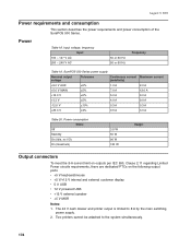
SurePOS 500 Series power supply Nominal output voltage Tolerance Continuous current Maximum current (indefinite) +5.0 V AUX ±5% 1.0 A 2.0 A +5.0 V MAIN ±5% 7.0 A 12.0 A +12.0 V ±5% 5.0 A 9.0 A +3.3 V ±5% 4.0 A 9.0 A -... Limited Power circuits requirements, there are dedicated PTCs on the following output ports: v +5 V keyboard/mouse v +5 V/+12 V internal and external customer display v 5 V USB v 12 V powered USB v +12 V external speaker v +5 V MSR Notes: 1. The 24 V cash drawer and... the power requirements and power consumption of the SurePOS 500 Series.
SurePOS 500 Series power supply Nominal output voltage Tolerance Continuous current Maximum current (indefinite) +5.0 V AUX ±5% 1.0 A 2.0 A +5.0 V MAIN ±5% 7.0 A 12.0 A +12.0 V ±5% 5.0 A 9.0 A +3.3 V ±5% 4.0 A 9.0 A -... Limited Power circuits requirements, there are dedicated PTCs on the following output ports: v +5 V keyboard/mouse v +5 V/+12 V internal and external customer display v 5 V USB v 12 V powered USB v +12 V external speaker v +5 V MSR Notes: 1. The 24 V cash drawer and... the power requirements and power consumption of the SurePOS 500 Series.

Service Guide
Page 212
Assignment of integrated customer-display connector pins Pin Connector 1 +5 V dc at 0.5 A maximum 2 Transmit data 3 Integrated customer display present 4 Ground 186 Assignment of cash drawer connector pins Pin Connector 1 Ground 2 Sensor 3 Open signal 4 +24 V dc Integrated customer display connector To access this connector, you must remove the rear cover. 1 4 Table 36. Connector-pin assignments Cash drawer connector (2) August 3, 2006 41 Table 35.
Assignment of integrated customer-display connector pins Pin Connector 1 +5 V dc at 0.5 A maximum 2 Transmit data 3 Integrated customer display present 4 Ground 186 Assignment of cash drawer connector pins Pin Connector 1 Ground 2 Sensor 3 Open signal 4 +24 V dc Integrated customer display connector To access this connector, you must remove the rear cover. 1 4 Table 36. Connector-pin assignments Cash drawer connector (2) August 3, 2006 41 Table 35.


