Hardware Maintenance Manual
Page 4
... 2020 Inverter card 121 2030 LCD panel, LCD cable assembly, wireless LAN antenna assembly, hinges, and LCD cover. 122 3010 ThinkPad Dock II PCI cover. . . . . . 132 3020 ThinkPad Dock II top cover 133 Locations 136 Front view 136 Rear view 138 Bottom view 139 Parts list 140 Overall 140 LCD... FRUs 188 AC adapters 206 Keyboard 207 Recovery CDs 209 Miscellaneous parts 217 Optional FRUs 221 Common parts list 222 Notices 224 Trademarks 226 iv R50/R50p, R51 ...
... 2020 Inverter card 121 2030 LCD panel, LCD cable assembly, wireless LAN antenna assembly, hinges, and LCD cover. 122 3010 ThinkPad Dock II PCI cover. . . . . . 132 3020 ThinkPad Dock II top cover 133 Locations 136 Front view 136 Rear view 138 Bottom view 139 Parts list 140 Overall 140 LCD... FRUs 188 AC adapters 206 Keyboard 207 Recovery CDs 209 Miscellaneous parts 217 Optional FRUs 221 Common parts list 222 Notices 224 Trademarks 226 iv R50/R50p, R51 ...
Hardware Maintenance Manual
Page 30
... Distortion, deformation, or discoloration of a nonsupported device v Forgotten computer password (making the computer unusable) v Sticky keys caused by spilling a liquid onto the keyboard The following symptoms might indicate damage caused by the improper insertion of a PC Card or the installation of unauthorized service or modification. v If the spindle... and address Note for repair costs if the computer damage was subjected to excessive force, or dropped. 26 R50/R50p, R51 Series Read this first __ 2. Machine type, model number, and serial number __ 9. Date of service __ 3.
... Distortion, deformation, or discoloration of a nonsupported device v Forgotten computer password (making the computer unusable) v Sticky keys caused by spilling a liquid onto the keyboard The following symptoms might indicate damage caused by the improper insertion of a PC Card or the installation of unauthorized service or modification. v If the spindle... and address Note for repair costs if the computer damage was subjected to excessive force, or dropped. 26 R50/R50p, R51 Series Read this first __ 2. Machine type, model number, and serial number __ 9. Date of service __ 3.
Hardware Maintenance Manual
Page 36
..." timer in screen blank mode: v The LCD is powered off . To end screen blank mode and resume normal operation, press any operation with the keyboard, the TrackPoint, the hard disk, the parallel connector, or the diskette drive within that the battery power is low. (Alternatively, if Hibernate when battery ...Fn+F3, v The LCD backlight turns off . Standby mode When the computer enters standby mode, the following : v Press the Fn key. 32 R50/R50p, R51 Series Note: If you are using the ACPI operating system, you can change the action of the following events occur in addition to return from...
..." timer in screen blank mode: v The LCD is powered off . To end screen blank mode and resume normal operation, press any operation with the keyboard, the TrackPoint, the hard disk, the parallel connector, or the diskette drive within that the battery power is low. (Alternatively, if Hibernate when battery ...Fn+F3, v The LCD backlight turns off . Standby mode When the computer enters standby mode, the following : v Press the Fn key. 32 R50/R50p, R51 Series Note: If you are using the ACPI operating system, you can change the action of the following events occur in addition to return from...
Hardware Maintenance Manual
Page 37
... system status is restored from standby mode and resumes operation: v The ring indicator (RI) is docked to the docking station, do any operation with the keyboard, the TrackPoint, the hard disk drive, the parallel connector, or the diskette drive within that causes the system to reenter operation mode. Pressing Fn+F4...
... system status is restored from standby mode and resumes operation: v The ring indicator (RI) is docked to the docking station, do any operation with the keyboard, the TrackPoint, the hard disk drive, the parallel connector, or the diskette drive within that causes the system to reenter operation mode. Pressing Fn+F4...
Hardware Maintenance Manual
Page 40
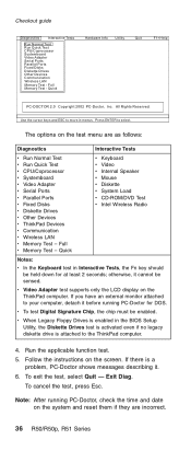
...v CD-ROM/DVD Test v Intel Wireless Radio Notes: v In the Keyboard test in Interactive Tests, the Fn key should be enabled. Follow the instructions...v CPU/Coprocessor v Systemboard v Video Adapter v Serial Ports v Parallel Ports v Fixed Disks v Diskette Drives v Other Devices v ThinkPad Devices v Communication v Wireless LAN v Memory Test - To exit the test, select Quit - Full v Memory Test - v ...test supports only the LCD display on the test menu are incorrect. 36 R50/R50p, R51 Series Press ENTER to move in the BIOS Setup Utility, the Diskette Drives test is activated...
...v CD-ROM/DVD Test v Intel Wireless Radio Notes: v In the Keyboard test in Interactive Tests, the Fn key should be enabled. Follow the instructions...v CPU/Coprocessor v Systemboard v Video Adapter v Serial Ports v Parallel Ports v Fixed Disks v Diskette Drives v Other Devices v ThinkPad Devices v Communication v Wireless LAN v Memory Test - To exit the test, select Quit - Full v Memory Test - v ...test supports only the LCD display on the test menu are incorrect. 36 R50/R50p, R51 Series Press ENTER to move in the BIOS Setup Utility, the Diskette Drives test is activated...
Hardware Maintenance Manual
Page 45
ThinkPad R50/R50p and R51 Series Product overview 43 Specifications 43...67 1020 Ultrabay Enhanced device 68 1030 Hard disk drive 69 1040 DIMM (optional 71 1050 Keyboard 72 1060 DIMM (standard 76 1070 Modem daughter card (MDC/MDC-2) . . . 77 1080 Bluetooth/Modem daughter... card (BMDC/BMDC-2 79 1090 Keyboard bezel 81 1100 Mini PCI adapter 85 1110 Fan assembly 89 1120 CPU 90 1130 Backup..., hinges, and LCD cover. 122 3010 ThinkPad Dock II PCI cover. . . . . . 132 3020 ThinkPad Dock II top cover 133 Locations 136 © Lenovo 2005. Portions ©...
ThinkPad R50/R50p and R51 Series Product overview 43 Specifications 43...67 1020 Ultrabay Enhanced device 68 1030 Hard disk drive 69 1040 DIMM (optional 71 1050 Keyboard 72 1060 DIMM (standard 76 1070 Modem daughter card (MDC/MDC-2) . . . 77 1080 Bluetooth/Modem daughter... card (BMDC/BMDC-2 79 1090 Keyboard bezel 81 1100 Mini PCI adapter 85 1110 Fan assembly 89 1120 CPU 90 1130 Backup..., hinges, and LCD cover. 122 3010 ThinkPad Dock II PCI cover. . . . . . 132 3020 ThinkPad Dock II top cover 133 Locations 136 © Lenovo 2005. Portions ©...
Hardware Maintenance Manual
Page 46
... IPS TFT AC adapters Keyboard Recovery CDs For Windows XP Professional (R50/R50p series For Windows XP Professional (R51 series) For Windows XP Home Edition (R50/R50p series For Windows XP Home Edition (R51 series) Miscellaneous parts Optional FRUs Common parts list Tools Power cords (system Power cords (ThinkPad Dock and ThinkPad Dock II Notices...
... IPS TFT AC adapters Keyboard Recovery CDs For Windows XP Professional (R50/R50p series For Windows XP Professional (R51 series) For Windows XP Home Edition (R50/R50p series For Windows XP Home Edition (R51 series) Miscellaneous parts Optional FRUs Common parts list Tools Power cords (system Power cords (ThinkPad Dock and ThinkPad Dock II Notices...
Hardware Maintenance Manual
Page 53
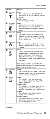
... could cause drive errors. Blinking orange: The battery needs to use. The ac adapter has charged the battery completely. Green: The computer is on the keyboard is enabled. To enable or disable Caps Lock mode, press the Caps Lock key. When the indicator starts blinking orange, the computer beeps three times...
... could cause drive errors. Blinking orange: The battery needs to use. The ac adapter has charged the battery completely. Green: The computer is on the keyboard is enabled. To enable or disable Caps Lock mode, press the Caps Lock key. When the indicator starts blinking orange, the computer beeps three times...
Hardware Maintenance Manual
Page 55
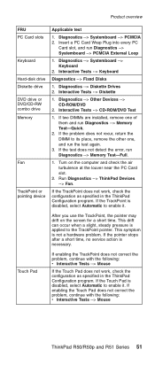
... Devices --> CD-ROM/DVD 2. If enabling the Touch Pad does not correct the problem, continue with the following : v Interactive Tests --> Mouse ThinkPad R50/R50p and R51 Series 51 Interactive Tests --> Keyboard Diagnostics --> Fixed Disks 1. If the test does not detect the error, run Diagnostics --> Memory Test-Quick. 2. If the TrackPoint does not work...
... Devices --> CD-ROM/DVD 2. If enabling the Touch Pad does not correct the problem, continue with the following : v Interactive Tests --> Mouse ThinkPad R50/R50p and R51 Series 51 Interactive Tests --> Keyboard Diagnostics --> Fixed Disks 1. If the test does not detect the error, run Diagnostics --> Memory Test-Quick. 2. If the TrackPoint does not work...
Hardware Maintenance Manual
Page 59
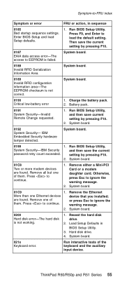
...; Load Setup Defaults in sequence 0185 Bad startup sequence settings. ThinkPad R50/R50p and R51 Series 55 Then save current setting by pressing F10. 2. Remove one of them . System board. 021x Keyboard error. System board. 0199 1. Run BIOS Setup Utility, System Security-IBM Security password retry count exceeded. Remove all but one Ethernet devices...
...; Load Setup Defaults in sequence 0185 Bad startup sequence settings. ThinkPad R50/R50p and R51 Series 55 Then save current setting by pressing F10. 2. Remove one of them . System board. 021x Keyboard error. System board. 0199 1. Run BIOS Setup Utility, System Security-IBM Security password retry count exceeded. Remove all but one Ethernet devices...
Hardware Maintenance Manual
Page 76
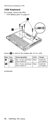
LCD. Step Icon 1 3 1a Screw (quantity) Color M2 × 12 mm, bind-head, Black nylon-coated (3) M2 × 12 mm, bind-head, Black nylon-coated (1) Torque 0.245 Nm (2.5 kgfcm) 0.245 Nm (2.5 kgfcm) (continued) 72 R50/R50p, R51 Series Removing and replacing a FRU 1050 Keyboard For access, remove this FRU: v "1010 Battery pack" on page 67 1 1a Screw 1a is only for the models with 14.1-in.
LCD. Step Icon 1 3 1a Screw (quantity) Color M2 × 12 mm, bind-head, Black nylon-coated (3) M2 × 12 mm, bind-head, Black nylon-coated (1) Torque 0.245 Nm (2.5 kgfcm) 0.245 Nm (2.5 kgfcm) (continued) 72 R50/R50p, R51 Series Removing and replacing a FRU 1050 Keyboard For access, remove this FRU: v "1010 Battery pack" on page 67 1 1a Screw 1a is only for the models with 14.1-in.
Hardware Maintenance Manual
Page 77
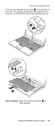
Removing and replacing a FRU Press the part indicated by the arrow 2 in the direction of the keyboard pops out. 2 4 3 When installing: Make sure that the front side of the arrow. This releases the latches of the keyboard from the frame, so that the connector 4 is firmly attached. ThinkPad R50/R50p and R51 Series 73
Removing and replacing a FRU Press the part indicated by the arrow 2 in the direction of the keyboard pops out. 2 4 3 When installing: Make sure that the front side of the arrow. This releases the latches of the keyboard from the frame, so that the connector 4 is firmly attached. ThinkPad R50/R50p and R51 Series 73
Hardware Maintenance Manual
Page 78
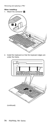
Install the keyboard so that the keyboard edges are under the frame. 2 (continued) 74 R50/R50p, R51 Series Removing and replacing a FRU When installing: 1. Attach the connector 1 . 1 2.
Install the keyboard so that the keyboard edges are under the frame. 2 (continued) 74 R50/R50p, R51 Series Removing and replacing a FRU When installing: 1. Attach the connector 1 . 1 2.
Hardware Maintenance Manual
Page 79
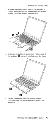
Make sure that the front edge of the keyboard is housed firmly, gently press the keys with the keyboard. Removing and replacing a FRU 3. Secure the keyboard from the underside of the keyboard b are firmly attached under the frame. ThinkPad R50/R50p and R51 Series 75 To make sure that all the projections on the front side of the computer, using the new screws provided with your fingers and try to slide the keyboard towards you. 3 3 4. b b 5.
Make sure that the front edge of the keyboard is housed firmly, gently press the keys with the keyboard. Removing and replacing a FRU 3. Secure the keyboard from the underside of the keyboard b are firmly attached under the frame. ThinkPad R50/R50p and R51 Series 75 To make sure that all the projections on the front side of the computer, using the new screws provided with your fingers and try to slide the keyboard towards you. 3 3 4. b b 5.
Hardware Maintenance Manual
Page 80
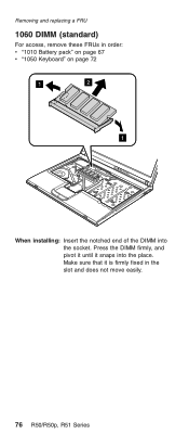
Press the DIMM firmly, and pivot it until it is firmly fixed in order: v "1010 Battery pack" on page 67 v "1050 Keyboard" on page 72 1 2 1 When installing: Insert the notched end of the DIMM into the place. Make sure that it snaps into the socket. Removing and replacing a FRU 1060 DIMM (standard) For access, remove these FRUs in the slot and does not move easily. 76 R50/R50p, R51 Series
Press the DIMM firmly, and pivot it until it is firmly fixed in order: v "1010 Battery pack" on page 67 v "1050 Keyboard" on page 72 1 2 1 When installing: Insert the notched end of the DIMM into the place. Make sure that it snaps into the socket. Removing and replacing a FRU 1060 DIMM (standard) For access, remove these FRUs in the slot and does not move easily. 76 R50/R50p, R51 Series
Hardware Maintenance Manual
Page 81
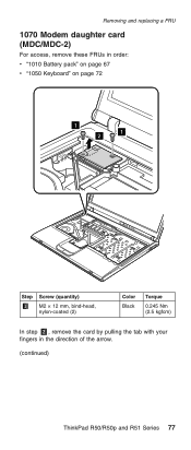
Removing and replacing a FRU 1070 Modem daughter card (MDC/MDC-2) For access, remove these FRUs in order: v "1010 Battery pack" on page 67 v "1050 Keyboard" on page 72 1 2 1 Step 1 Screw (quantity) M2 × 12 mm, bind-head, nylon-coated (2) Color Black Torque 0.245 Nm (2.5 kgfcm) In step 2 , remove the card by pulling the tab with your fingers in the direction of the arrow. (continued) ThinkPad R50/R50p and R51 Series 77
Removing and replacing a FRU 1070 Modem daughter card (MDC/MDC-2) For access, remove these FRUs in order: v "1010 Battery pack" on page 67 v "1050 Keyboard" on page 72 1 2 1 Step 1 Screw (quantity) M2 × 12 mm, bind-head, nylon-coated (2) Color Black Torque 0.245 Nm (2.5 kgfcm) In step 2 , remove the card by pulling the tab with your fingers in the direction of the arrow. (continued) ThinkPad R50/R50p and R51 Series 77
Hardware Maintenance Manual
Page 83
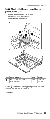
Removing and replacing a FRU 1080 Bluetooth/Modem daughter card (BMDC/BMDC-2) For access, remove these FRUs in order: v "1010 Battery pack" on page 67 v "1050 Keyboard" on page 72 1 2 1 Step 1 Screw (quantity) M2 × 12 mm, bind-head, nylon-coated (2) Color Black Torque 0.245 Nm (2.5 kgfcm) In step 2 , remove the card by pulling the tab with your fingers in the direction of the arrow. (continued) ThinkPad R50/R50p and R51 Series 79
Removing and replacing a FRU 1080 Bluetooth/Modem daughter card (BMDC/BMDC-2) For access, remove these FRUs in order: v "1010 Battery pack" on page 67 v "1050 Keyboard" on page 72 1 2 1 Step 1 Screw (quantity) M2 × 12 mm, bind-head, nylon-coated (2) Color Black Torque 0.245 Nm (2.5 kgfcm) In step 2 , remove the card by pulling the tab with your fingers in the direction of the arrow. (continued) ThinkPad R50/R50p and R51 Series 79
Hardware Maintenance Manual
Page 85
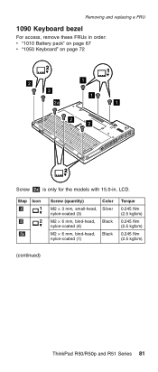
LCD. Removing and replacing a FRU 1090 Keyboard bezel For access, remove these FRUs in order: v "1010 Battery pack" on page 67 v "1050 Keyboard" on page 72 2 2 2 2a 1 1 1 1 2 2 2 Screw 2a is only for the models with 15.0-in. Step Icon 1 1 2 2 2a Screw (quantity) Color M2 × 3 mm, small-head, Silver nylon-coated (3) M2 × 6 mm, bind-head, Black nylon-coated (4) M2 × 6 mm, bind-head, Black nylon-coated (1) Torque 0.245 Nm (2.5 kgfcm) 0.245 Nm (2.5 kgfcm) 0.245 Nm (2.5 kgfcm) (continued) ThinkPad R50/R50p and R51 Series 81
LCD. Removing and replacing a FRU 1090 Keyboard bezel For access, remove these FRUs in order: v "1010 Battery pack" on page 67 v "1050 Keyboard" on page 72 2 2 2 2a 1 1 1 1 2 2 2 Screw 2a is only for the models with 15.0-in. Step Icon 1 1 2 2 2a Screw (quantity) Color M2 × 3 mm, small-head, Silver nylon-coated (3) M2 × 6 mm, bind-head, Black nylon-coated (4) M2 × 6 mm, bind-head, Black nylon-coated (1) Torque 0.245 Nm (2.5 kgfcm) 0.245 Nm (2.5 kgfcm) 0.245 Nm (2.5 kgfcm) (continued) ThinkPad R50/R50p and R51 Series 81
Hardware Maintenance Manual
Page 87
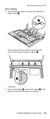
Removing and replacing a FRU When installing: 1. ThinkPad R50/R50p and R51 Series 83 a (continued) 2. Press the left edges 2 and the front edges 3 of the keyboard bezel as in palce 1 . 1 While inserting the three latches, align the top-left corner of the keyboard bezel until the latches are fixed in figure a . Place the keybard bezel so that the three latches are snapped.
Removing and replacing a FRU When installing: 1. ThinkPad R50/R50p and R51 Series 83 a (continued) 2. Press the left edges 2 and the front edges 3 of the keyboard bezel as in palce 1 . 1 While inserting the three latches, align the top-left corner of the keyboard bezel until the latches are fixed in figure a . Place the keybard bezel so that the three latches are snapped.
Hardware Maintenance Manual
Page 88
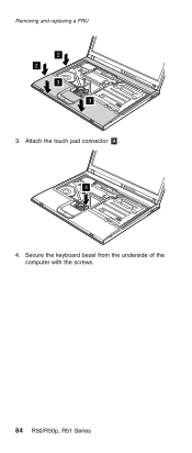
Attach the touch pad connector 4 . 4 4. Secure the keyboard bezel from the underside of the computer with the screws. 84 R50/R50p, R51 Series Removing and replacing a FRU 2 2 3 3 3.
Attach the touch pad connector 4 . 4 4. Secure the keyboard bezel from the underside of the computer with the screws. 84 R50/R50p, R51 Series Removing and replacing a FRU 2 2 3 3 3.
