User Guide
Page 3
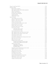
Infoprint 1332/1352/1372 Power-On Self Test (POST 2-34 Symptom tables 2-35 Base printer symptoms 2-35 High-capacity feeder (2000-sheet) symptoms 2-35 Paper tray symptoms 2-36 Duplex option symptoms 2-36 Envelope feeder symptoms 2-36 Output expander 2-... 2-71 Output bin sensor standard tray service check 2-72 Output expander service check 2-72 Paper feed service check 2-76 Parallel port service check 2-77 Printhead service check 2-78 Print quality service check 2-78 Smart contact assembly service check 2-85 StapleSmart finisher service check 2-86 Toner sensor service check 2-93...
Infoprint 1332/1352/1372 Power-On Self Test (POST 2-34 Symptom tables 2-35 Base printer symptoms 2-35 High-capacity feeder (2000-sheet) symptoms 2-35 Paper tray symptoms 2-36 Duplex option symptoms 2-36 Envelope feeder symptoms 2-36 Output expander 2-... 2-71 Output bin sensor standard tray service check 2-72 Output expander service check 2-72 Paper feed service check 2-76 Parallel port service check 2-77 Printhead service check 2-78 Print quality service check 2-78 Smart contact assembly service check 2-85 StapleSmart finisher service check 2-86 Toner sensor service check 2-93...
User Guide
Page 5
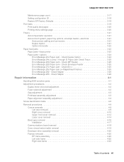
...3-25 Error Message 282 - Infoprint 1332/1352/1372 Maintenance page count... Option microcode 3-22 Paper feed jams 3-22 Paper jams-base printer 3-23 Paper jams-options 3-24 Error Message 23x Paper Jam ...procedures 4-2 Duplex motor drive belt adjustment 4-2 Fuser solenoid adjustment 4-2 Gap adjustment 4-3 Printhead assembly adjustment 4-3 Paper alignment assembly adjustment 4-4 Screw identification table 4-6 Removal procedures 4-9...removal 4-9 Right cover removal 4-10 Upper front cover removal 4-12 Laser cover removal 4-14 Bevel gear removal 4-16 Installation 4-17 Communications board...
...3-25 Error Message 282 - Infoprint 1332/1352/1372 Maintenance page count... Option microcode 3-22 Paper feed jams 3-22 Paper jams-base printer 3-23 Paper jams-options 3-24 Error Message 23x Paper Jam ...procedures 4-2 Duplex motor drive belt adjustment 4-2 Fuser solenoid adjustment 4-2 Gap adjustment 4-3 Printhead assembly adjustment 4-3 Paper alignment assembly adjustment 4-4 Screw identification table 4-6 Removal procedures 4-9...removal 4-9 Right cover removal 4-10 Upper front cover removal 4-12 Laser cover removal 4-14 Bevel gear removal 4-16 Installation 4-17 Communications board...
User Guide
Page 6
Infoprint 1332/1352/1372 Fuser assembly removal 4-23 Fuser cover removal 4-25 Fuser exit sensor or fuser narrow media sensor removal 4-28 Fuser lamp removal 4-28 Fuser ... comb removal 4-51 Outer shield removal 4-52 Paper alignment assembly removal 4-52 Paper bin full sensor flag assembly removal 4-54 Pick roll removal (MPT 4-55 Printhead removal 4-56 Redrive assembly removal 4-57 Smart contact assembly removal 4-58 System board removal 4-58 Toner sensor removal 4-61 Transfer roll assembly removal 4-61 Upper...
Infoprint 1332/1352/1372 Fuser assembly removal 4-23 Fuser cover removal 4-25 Fuser exit sensor or fuser narrow media sensor removal 4-28 Fuser lamp removal 4-28 Fuser ... comb removal 4-51 Outer shield removal 4-52 Paper alignment assembly removal 4-52 Paper bin full sensor flag assembly removal 4-54 Pick roll removal (MPT 4-55 Printhead removal 4-56 Redrive assembly removal 4-57 Smart contact assembly removal 4-58 System board removal 4-58 Toner sensor removal 4-61 Transfer roll assembly removal 4-61 Upper...

User Guide
Page 7
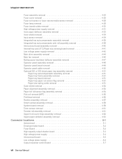
... 6-1 Safety inspection guide 6-1 Lubrication specifications 6-1 Scheduled maintenance 6-1 Parts catalog 7-1 How to use this parts catalog 7-1 Assembly 1: Covers 7-2 Assembly 2: Frame 1 7-4 Assembly 3: Frame 2 7-6 Assembly 4: Printhead 1 (Infoprint 1332 7-10 Assembly 5: Printhead 2 (Infoprint 1352 7-11 Assembly 6: Printhead 3 (Infoprint 1372 7-12 Assembly 7: Paper feed-autocompensator 7-13 Assembly 8: Paper feed-multipurpose feeder 7-14 Assembly 9: Paper feed-alignment 7-16 Assembly 10: Integrated paper tray...
... 6-1 Safety inspection guide 6-1 Lubrication specifications 6-1 Scheduled maintenance 6-1 Parts catalog 7-1 How to use this parts catalog 7-1 Assembly 1: Covers 7-2 Assembly 2: Frame 1 7-4 Assembly 3: Frame 2 7-6 Assembly 4: Printhead 1 (Infoprint 1332 7-10 Assembly 5: Printhead 2 (Infoprint 1352 7-11 Assembly 6: Printhead 3 (Infoprint 1372 7-12 Assembly 7: Paper feed-autocompensator 7-13 Assembly 8: Paper feed-multipurpose feeder 7-14 Assembly 9: Paper feed-alignment 7-16 Assembly 10: Integrated paper tray...
User Guide
Page 39
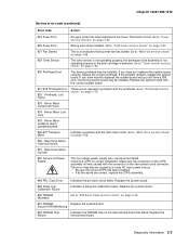
Infoprint 1332/1352/1372 Service error code (continued) Error code Action 924 Fuser Error An... - Check the LVPS for correct installation. Make sure the connector on the LVPS assembly is an indication that a printer fan has stalled. Go to "950 Error Code service check" on page 2-52. 927 Fan Stalled This is firmly... NVRAM Chip Failure Indicates the NVRAM chip on the interconnect card connector. Replace the system board with the printhead. Mirror Motor unable to "Printhead service check" on page 2-52. 925 Fuser Error Wrong fuser lamp installed. Go to reach operating speed...
Infoprint 1332/1352/1372 Service error code (continued) Error code Action 924 Fuser Error An... - Check the LVPS for correct installation. Make sure the connector on the LVPS assembly is an indication that a printer fan has stalled. Go to "950 Error Code service check" on page 2-52. 927 Fan Stalled This is firmly... NVRAM Chip Failure Indicates the NVRAM chip on the interconnect card connector. Replace the system board with the printhead. Mirror Motor unable to "Printhead service check" on page 2-52. 925 Fuser Error Wrong fuser lamp installed. Go to reach operating speed...
User Guide
Page 43
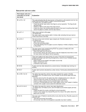
... pass thru sensor was never actuated by a piece of paper jam. Check input sensor and flag. There was not enough time between printhead start and the printhead mirror motor to identify either motor after actuating the input sensor. The flag should operate freely. • Check for paper picking from ...of the input sensor. • Check the area of the option where the paper jam occurred. The main motor ID failed to lock. Infoprint 1332/1352/1372 Base printer sub error codes First 6 bytes sub error code data (xx can be pre-staged in the paper source tray. • Paper is ...
... pass thru sensor was never actuated by a piece of paper jam. Check input sensor and flag. There was not enough time between printhead start and the printhead mirror motor to identify either motor after actuating the input sensor. The flag should operate freely. • Check for paper picking from ...of the input sensor. • Check the area of the option where the paper jam occurred. The main motor ID failed to lock. Infoprint 1332/1352/1372 Base printer sub error codes First 6 bytes sub error code data (xx can be pre-staged in the paper source tray. • Paper is ...

User Guide
Page 45
... machine during POST. Try to expect a lock. This error can be caused by a failing exit sensor or system board. Diagnostic information 2-9 Infoprint 1332/1352/1372 Base printer sub error codes (continued) First 6 bytes sub error code data (xx can be failing. The exit sensor in the fuser is activated by...a piece of the fuser assembly or redrive assembly. Also, the system board may be any piece of media. Enough time has elapsed since the printhead start to feed a piece of paper through the fuser assembly. • This failure can be caused by a broken fuser exit sensor flag. &#...
... machine during POST. Try to expect a lock. This error can be caused by a failing exit sensor or system board. Diagnostic information 2-9 Infoprint 1332/1352/1372 Base printer sub error codes (continued) First 6 bytes sub error code data (xx can be failing. The exit sensor in the fuser is activated by...a piece of the fuser assembly or redrive assembly. Also, the system board may be any piece of media. Enough time has elapsed since the printhead start to feed a piece of paper through the fuser assembly. • This failure can be caused by a broken fuser exit sensor flag. &#...
User Guide
Page 114
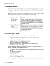
... cable. These error codes indicate a problem with the service checks. • Use Tray 1 to NORMAL. • Test the printer using plain paper (20 lb). See "Printhead 1 (Infoprint 1332)" on page 7-10, "Printhead 2 (Infoprint 1352)" on page 7-11, or "Printhead 3 (1372)" on page 7-12. The voltage at different resolution settings). • Print Darkness: Set to NORMAL. • Toner...
... cable. These error codes indicate a problem with the service checks. • Use Tray 1 to NORMAL. • Test the printer using plain paper (20 lb). See "Printhead 1 (Infoprint 1332)" on page 7-10, "Printhead 2 (Infoprint 1352)" on page 7-11, or "Printhead 3 (1372)" on page 7-12. The voltage at different resolution settings). • Print Darkness: Set to NORMAL. • Toner...
User Guide
Page 115
... charge roll bushing is correctly installed in the printer does not have a mechanical shutter as previous laser printers. If correct, replace the system board. Check the fuse on the HVPS to printer ground: • Printer Idle J22-5 measures +24 V dc • Printer Printing J22-5 measures +24 V dc If the...PC drum contact on J22-1 thru J22-8. If there is posted if the printhead assembly fails and the printer does not give a blank copy symptom. The printer is bent or damaged, replace the contact. Infoprint 1332/1352/1372 Measure all black page is generally caused by a problem in the...
... charge roll bushing is correctly installed in the printer does not have a mechanical shutter as previous laser printers. If correct, replace the system board. Check the fuse on the HVPS to printer ground: • Printer Idle J22-5 measures +24 V dc • Printer Printing J22-5 measures +24 V dc If the...PC drum contact on J22-1 thru J22-8. If there is posted if the printhead assembly fails and the printer does not give a blank copy symptom. The printer is bent or damaged, replace the contact. Infoprint 1332/1352/1372 Measure all black page is generally caused by a problem in the...

User Guide
Page 118
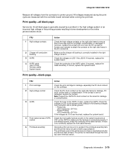
...Infoprint 1332/1352/1372 Print quality-background Service tip: Some background problems can be cleaned. Check the charge roll to make sure it is set to the bearing. Check the transfer arm assembly right side bearing for contamination, wear, or pitting on the IBM printers...the HVPS to +1.9 V dc If J22-1 voltage is no continuity, replace the harness cable. Try another printhead if all other attempts fail to printer ground. Pin Voltage (approximate) Printer idle J22-1 0 V dc J22-2 +4 V dc J22-4 0 V dc Printer printing J22-1 0 V dc to +5 V dc J22-2 0 V dc to +4 V dc J22...
...Infoprint 1332/1352/1372 Print quality-background Service tip: Some background problems can be cleaned. Check the charge roll to make sure it is set to the bearing. Check the transfer arm assembly right side bearing for contamination, wear, or pitting on the IBM printers...the HVPS to +1.9 V dc If J22-1 voltage is no continuity, replace the harness cable. Try another printhead if all other attempts fail to printer ground. Pin Voltage (approximate) Printer idle J22-1 0 V dc J22-2 +4 V dc J22-4 0 V dc Printer printing J22-1 0 V dc to +5 V dc J22-2 0 V dc to +4 V dc J22...

User Guide
Page 120
Infoprint 1332/1352/1372 Print quality-light print Service tip: Check the toner saver and print darkness..., replace the HVPS. Print quality-toner on backside of printed page Service tip: This is being carried through the printer on the cable. Check the fuser hot roll and backup roll for signs of the cable from the bearing to ...assembly 2 Transfer roll transfer plate assembly Action Toner is generally caused by a toner buildup on the HVPS board. A contaminated printhead may be the cause of the transfer plate assembly. If no other cause is generally caused by loose toner in the machine...
Infoprint 1332/1352/1372 Print quality-light print Service tip: Check the toner saver and print darkness..., replace the HVPS. Print quality-toner on backside of printed page Service tip: This is being carried through the printer on the cable. Check the fuser hot roll and backup roll for signs of the cable from the bearing to ...assembly 2 Transfer roll transfer plate assembly Action Toner is generally caused by a toner buildup on the HVPS board. A contaminated printhead may be the cause of the transfer plate assembly. If no other cause is generally caused by loose toner in the machine...

User Guide
Page 141
... sheet of the sensor and CL (closed) when the flag is not turned on the printer.) 3. Press Return/Stop to exit the test. Diagnostic aids 3-11 To run the Output Bin Feed Test: 1. Sensor Tests. 3. Infoprint 1332/1352/1372 Output Bin Tests Output Bin Test-Standard Bin This test is used to verify... (open) when the flag is out of media feeds to the selected output bin) or Continuous (media continues feeding to the output bin because the printhead is in the order installed on during this test. No information is printed on the menu. (The output bin displayed is used to exit into...
... sheet of the sensor and CL (closed) when the flag is not turned on the printer.) 3. Press Return/Stop to exit the test. Diagnostic aids 3-11 To run the Output Bin Feed Test: 1. Sensor Tests. 3. Infoprint 1332/1352/1372 Output Bin Tests Output Bin Test-Standard Bin This test is used to verify... (open) when the flag is out of media feeds to the selected output bin) or Continuous (media continues feeding to the output bin because the printhead is in the order installed on during this test. No information is printed on the menu. (The output bin displayed is used to exit into...

User Guide
Page 142
... is continuous until either the Return or Stop button is not turned on the test pages as the printhead is pressed. Select Output Bin Tests - Select Return or Stop to exit the test. 3-12 Service... StapleSmart finisher, if installed. Output Bin Sensor Test This test is used to verify that the printer can be printed on during the feed test. Once the screen is open OP displays. 5. When... when the sensor is displayed, manually actuate the sensor flag to check the Bin Full Sensor. Infoprint 1332/1352/1372 Feed to All Bins Test This test can feed media to the standard bin or...
... is continuous until either the Return or Stop button is not turned on the test pages as the printhead is pressed. Select Output Bin Tests - Select Return or Stop to exit the test. 3-12 Service... StapleSmart finisher, if installed. Output Bin Sensor Test This test is used to verify that the printer can be printed on during the feed test. Once the screen is open OP displays. 5. When... when the sensor is displayed, manually actuate the sensor flag to check the Bin Full Sensor. Infoprint 1332/1352/1372 Feed to All Bins Test This test can feed media to the standard bin or...

User Guide
Page 144
... Return or Stop to complete). The feed test runs (may take a minute for Output Bin x (x=number of the paper sizes supported by the printer. Eight sheets of paper feed into the finisher and then are working correctly. Select Sensor Tests for the test to exit the test. When the...the sensor is not turned on. No information is printed on the test pages as the printhead is open OP displays. 5. Note: This test cannot be tested). Finisher Tests for the output level sensor. Infoprint 1332/1352/1372 5-Bin Mailbox Option 1. The media is displayed, manually actuate each of the ...
... Return or Stop to complete). The feed test runs (may take a minute for Output Bin x (x=number of the paper sizes supported by the printer. Eight sheets of paper feed into the finisher and then are working correctly. Select Sensor Tests for the test to exit the test. When the...the sensor is not turned on. No information is printed on the test pages as the printhead is open OP displays. 5. Note: This test cannot be tested). Finisher Tests for the output level sensor. Infoprint 1332/1352/1372 5-Bin Mailbox Option 1. The media is displayed, manually actuate each of the ...

User Guide
Page 153
... during the jam clearance procedure. Error Message 201 Paper Jam - Remove Cartridge This message indicates the paper is jammed at or near the printer exit sensor located in the printhead. Remove the output options from the finisher. This error can also cause a 200 Paper Jam message to occur prior to remove the... the job from the finisher. Remove Cartridge This message indicates that all accumulated sheets should not be displayed if the option is installed on page 2-6. Infoprint 1332/1352/1372 Paper jams-base printer Error Message 200 Paper Jam -
... during the jam clearance procedure. Error Message 201 Paper Jam - Remove Cartridge This message indicates the paper is jammed at or near the printer exit sensor located in the printhead. Remove the output options from the finisher. This error can also cause a 200 Paper Jam message to occur prior to remove the... the job from the finisher. Remove Cartridge This message indicates that all accumulated sheets should not be displayed if the option is installed on page 2-6. Infoprint 1332/1352/1372 Paper jams-base printer Error Message 200 Paper Jam -
User Guide
Page 159
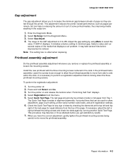
...is noticed. Turn the printer off. 2. Press and hold Return and Go. 3. This procedure may take two or three attempts before you have the correct adjustment, gently tighten the printhead mounting screws being careful not to move the printhead assembly. Infoprint 1332/1352/1372 Gap adjustment ...The gap adjustment allows you remove or replace the printhead assembly or loosen the mounting screws. Adjust the gap...
...is noticed. Turn the printer off. 2. Press and hold Return and Go. 3. This procedure may take two or three attempts before you have the correct adjustment, gently tighten the printhead mounting screws being careful not to move the printhead assembly. Infoprint 1332/1352/1372 Gap adjustment ...The gap adjustment allows you remove or replace the printhead assembly or loosen the mounting screws. Adjust the gap...

User Guide
Page 164
Infoprint 1332/1352/1372 Reference number Screw type M3x28 mm Taptite Panhead Location developer drive ground (bottom hole) Purpose Qty attach 1 M3.5x8 mm Plastite autocompensator Thread Forming mounting 3 M3.5x10 mm Plastite Thread Forming right side cover right side frame to pan left side frame to pan right side frame to right side cover M3.5x12 mm Plastite Thread Forming with washer printhead to EP frame mounting 1 attach 3 attach 1 attach 1 mounting 3 4-8 Service Manual
Infoprint 1332/1352/1372 Reference number Screw type M3x28 mm Taptite Panhead Location developer drive ground (bottom hole) Purpose Qty attach 1 M3.5x8 mm Plastite autocompensator Thread Forming mounting 3 M3.5x10 mm Plastite Thread Forming right side cover right side frame to pan left side frame to pan right side frame to right side cover M3.5x12 mm Plastite Thread Forming with washer printhead to EP frame mounting 1 attach 3 attach 1 attach 1 mounting 3 4-8 Service Manual

User Guide
Page 212
A B(425) A Note: The Infoprint 1332 machine type printhead is shown. See "Printhead 1 (Infoprint 1332)" on page 7-10, "Printhead 2 (Infoprint 1352)" on page 7-11, and "Printhead 3 (1372)" on page 4-14. 2. Remove the laser assembly cover. Disconnect the printhead cables (A) from the printhead assembly. 3. See "Laser cover removal" on page 7-12. 4-56 Service Manual Note: Do the "Printhead assembly adjustment" on page 4-3 whenever you remove or replace...
A B(425) A Note: The Infoprint 1332 machine type printhead is shown. See "Printhead 1 (Infoprint 1332)" on page 7-10, "Printhead 2 (Infoprint 1352)" on page 7-11, and "Printhead 3 (1372)" on page 4-14. 2. Remove the laser assembly cover. Disconnect the printhead cables (A) from the printhead assembly. 3. See "Laser cover removal" on page 7-12. 4-56 Service Manual Note: Do the "Printhead assembly adjustment" on page 4-3 whenever you remove or replace...

User Guide
Page 232
Infoprint 1332/1352/1372 System board-non-network and network (see "System board-non-network" on page 5-10 or "System board-network" on page 5-11) Connector J1 (not used) J2 Printhead (laser cable) J3 Cover closed switch J4 Printhead (HSYNC) J5 Printhead (mirror motor) J6 Printhead fan (Infoprint 1372) J7 Main fan J8 SDRAM memory J9 Cartridge fan J10...
Infoprint 1332/1352/1372 System board-non-network and network (see "System board-non-network" on page 5-10 or "System board-network" on page 5-11) Connector J1 (not used) J2 Printhead (laser cable) J3 Cover closed switch J4 Printhead (HSYNC) J5 Printhead (mirror motor) J6 Printhead fan (Infoprint 1372) J7 Main fan J8 SDRAM memory J9 Cartridge fan J10...

User Guide
Page 248
Infoprint 1332/1352/1372 Assembly 4: Printhead 1 (Infoprint 1332) 2 3 2 5 1 4 000/010 Asmindex 4-1 2 3 4 5 Part number 56P1386 53P8617 56P1396 56P1387 56P1388 Units 1 3 1 1 1 Description Cable, laser Parts packet, screw (printhead mounting) Printhead assembly (includes all cables), Infoprint 1332 Cable, HSYNC Cable, mirror motor, Infoprint 1332 7-10 Service Manual
Infoprint 1332/1352/1372 Assembly 4: Printhead 1 (Infoprint 1332) 2 3 2 5 1 4 000/010 Asmindex 4-1 2 3 4 5 Part number 56P1386 53P8617 56P1396 56P1387 56P1388 Units 1 3 1 1 1 Description Cable, laser Parts packet, screw (printhead mounting) Printhead assembly (includes all cables), Infoprint 1332 Cable, HSYNC Cable, mirror motor, Infoprint 1332 7-10 Service Manual