Owner's Manual
Page 2
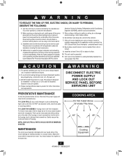
...combustion and exhausting of gasses through the flue (chimney) of fuel burning equipment to prevent backdrafting. protected branch circuit. 8. Install fan at the same time. WARNING DISCONNECT ELECTRIC POWER SUPPLY AND LOCK OUT SERVICE PANEL BEFORE SERVICING UNIT PREVENTATIVE MAINTENANCE A ...twist screwdriver. American Society for further information and requirements. Before servicing or cleaning the unit, switch power off power unit. 3. Installation work and electrical wiring must point upward. 4. When cutting or drilling into the slot in a manner intended by the National ...
...combustion and exhausting of gasses through the flue (chimney) of fuel burning equipment to prevent backdrafting. protected branch circuit. 8. Install fan at the same time. WARNING DISCONNECT ELECTRIC POWER SUPPLY AND LOCK OUT SERVICE PANEL BEFORE SERVICING UNIT PREVENTATIVE MAINTENANCE A ...twist screwdriver. American Society for further information and requirements. Before servicing or cleaning the unit, switch power off power unit. 3. Installation work and electrical wiring must point upward. 4. When cutting or drilling into the slot in a manner intended by the National ...
Owner's Manual
Page 3
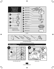
... time: 30 to 60 minutes NOTE: Remove all the parts. x5 A *B *C 3/8" Cable Connector x2 D Extra Screws * NOTE: Strain relief cable connector must be installed. Check all packing materials before installation. 2 J F Turn off the power source. 3 41949-01 09/09/2011 Loosen screws. E 95044-01-000 F 95022-01-000 G 75190-01-000 H 03242...
... time: 30 to 60 minutes NOTE: Remove all the parts. x5 A *B *C 3/8" Cable Connector x2 D Extra Screws * NOTE: Strain relief cable connector must be installed. Check all packing materials before installation. 2 J F Turn off the power source. 3 41949-01 09/09/2011 Loosen screws. E 95044-01-000 F 95022-01-000 G 75190-01-000 H 03242...
Owner's Manual
Page 5
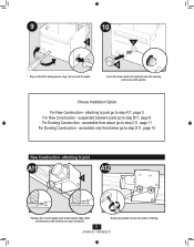
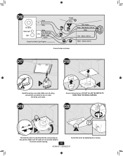
Choose Installation Option For New Construction - accessible only from above go to step D11, page 15 New Construction - Screw pre-loaded screws into the housing and secure ...
Choose Installation Option For New Construction - accessible only from above go to step D11, page 15 New Construction - Screw pre-loaded screws into the housing and secure ...
Owner's Manual
Page 6
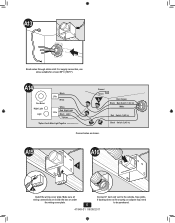
... Together Ground Green A Bare Copper Black Main Switch 1 (AC In) White Red Switch 1 (AC In) Black Switch 2 (AC In) Connect wires as shown. A15 A016 F H Install the wiring cover plate. Tape joints. A13 Route wires through strain relief. For supply connection, use wires suitable for at least 90º C (194º F).
... Together Ground Green A Bare Copper Black Main Switch 1 (AC In) White Red Switch 1 (AC In) Black Switch 2 (AC In) Connect wires as shown. A15 A016 F H Install the wiring cover plate. Tape joints. A13 Route wires through strain relief. For supply connection, use wires suitable for at least 90º C (194º F).
Owner's Manual
Page 9
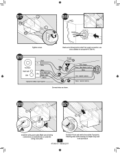
B20 B21 G H Install the wiring cover plate. Connect 4" duct and vent to be purchased. 9 41949-01 09/09/2011 Route wires through strain relief. B19 Fan Motor Night ...
B20 B21 G H Install the wiring cover plate. Connect 4" duct and vent to be purchased. 9 41949-01 09/09/2011 Route wires through strain relief. B19 Fan Motor Night ...
Owner's Manual
Page 13
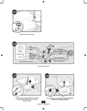
DO NOT ALLOW THE MOTOR TO HANG FROM THE WIRING HARNESS. 13 41949-01 09/09/2011 C21 Tighten the strain relief screws. C23 C24 G I H Install the wiring cover plate. C22 Fan Motor Night Light Light Black 2 Pin White 3 Pin White Red Night Light Black Light *Option *Option Fan & Main Light Together Ground Green A Bare Copper Black Main Switch 1 (AC In) White Red Switch 1 (AC In) Black Switch 2 (AC In) Connect wires as shown. Make sure all wiring connections are inside the box or under the wiring cover plate. Connect wiring harness.
DO NOT ALLOW THE MOTOR TO HANG FROM THE WIRING HARNESS. 13 41949-01 09/09/2011 C21 Tighten the strain relief screws. C23 C24 G I H Install the wiring cover plate. C22 Fan Motor Night Light Light Black 2 Pin White 3 Pin White Red Night Light Black Light *Option *Option Fan & Main Light Together Ground Green A Bare Copper Black Main Switch 1 (AC In) White Red Switch 1 (AC In) Black Switch 2 (AC In) Connect wires as shown. Make sure all wiring connections are inside the box or under the wiring cover plate. Connect wiring harness.
Owner's Manual
Page 15
If ducting does not fit securely, an adapter may need to duct connector. F Install the housing flush with the sheetrock and secure by tightening the pre-loaded screws into position above the ceiling D13 D14 2 1 Route wires through strain ...
If ducting does not fit securely, an adapter may need to duct connector. F Install the housing flush with the sheetrock and secure by tightening the pre-loaded screws into position above the ceiling D13 D14 2 1 Route wires through strain ...
Owner's Manual
Page 16
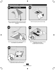
... motor by inserting the tabs and pushing up into position. D19 I J Reinstall the motor by tightening the 2 screws. 41949-01 09/09/2011 D17 D18 G H Install the wiring cover plate. D20 I Connect wiring harness.
... motor by inserting the tabs and pushing up into position. D19 I J Reinstall the motor by tightening the 2 screws. 41949-01 09/09/2011 D17 D18 G H Install the wiring cover plate. D20 I Connect wiring harness.
Owner's Manual
Page 18
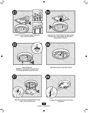
Slide light fixture over posts. WARNING: To reduce the risk of electrical shock, all 4 thumbscrews MUST be properly installed. E7 Install 2 Max 60 watt A-15 bulbs (Not Included). E5 Align posts A, B, C and D (stamped into motor housing) with slots on light fixture, and insert tabs into slots. ...
Slide light fixture over posts. WARNING: To reduce the risk of electrical shock, all 4 thumbscrews MUST be properly installed. E7 Install 2 Max 60 watt A-15 bulbs (Not Included). E5 Align posts A, B, C and D (stamped into motor housing) with slots on light fixture, and insert tabs into slots. ...
Owner's Manual
Page 20
...by repairs by persons not authorized by us, use of parts or accessories not authorized by us, mishandling, improper installation, modifications or damage to the Hunter bath exhaust fan while in your possession, or unreasonable use, including failure to avoid damage in transit since we ... in Memphis, Tennessee. To obtain servicing, contact the nearest Hunter authorized service center of purchase is not purchased and installed in China 20 41949-01 09/09/2011 © 2011 Hunter Fan Company Proof of the Hunter Fan Company Service Department, 2500 Frisco Avenue, Memphis, Tennessee 38114...
...by repairs by persons not authorized by us, use of parts or accessories not authorized by us, mishandling, improper installation, modifications or damage to the Hunter bath exhaust fan while in your possession, or unreasonable use, including failure to avoid damage in transit since we ... in Memphis, Tennessee. To obtain servicing, contact the nearest Hunter authorized service center of purchase is not purchased and installed in China 20 41949-01 09/09/2011 © 2011 Hunter Fan Company Proof of the Hunter Fan Company Service Department, 2500 Frisco Avenue, Memphis, Tennessee 38114...


