Hunter 81021 Support and Manuals
Get Help and Manuals for this Hunter item
View All Support Options Below
Free Hunter 81021 manuals!
Problems with Hunter 81021?
Ask a Question
Free Hunter 81021 manuals!
Problems with Hunter 81021?
Ask a Question
Popular Hunter 81021 Manual Pages
Owner's Manual - Page 1

Installation
Guide
ENGLISH
See page 2
Español
Vea la página 23
Français
Consulter la page 45
Model 81021 Victorian Bath Ventilator with Light
READ and SAVE THESE INSTRUCTIONS
1
43041-01 01/31/2008
Owner's Manual - Page 2
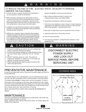
...This unit must point upward.
4. Please read specification label on the motor plate (located next to the receptacle). Warning
DISCONNECT ELECTRIC POWER SUPPLY AND LOCK OUT
SERVICE PANEL BEFORE SERVICING UNIT
PREVENTATIVE MAINTENANCE
A clean fan provides better service. You should replace the impeller at service panel and lock the service disconnecting means to prevent power from being...
Owner's Manual - Page 5

B
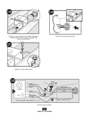
Insert the strain relief into the housing and secure with the washer.
accessible from below go to step C11, page 11 For Existing Construction - Choose Installation Option
For New Construction - attaching to joist fo to step B11, page 8 For Existing Construction - Use second if needed. suspended between joists go to step ...
Owner's Manual - Page 6

...
E
5/8 1/2
Position the correct depth mark at the bottom edge of the joist based on the thickness of your sheetrock.
A14
Fan Motor
F
Light
Black 2 Pin
White
White
3 Pin Black Light *Option
*Option Fan & Main Light Together
Ground Green
A
Bare Copper Black Main Switch 1 (AC In)
White
Black Switch 2 (AC In)
Connect wires as shown.
6
43041...
Owner's Manual - Page 9

Screws are not provided. Pull wires through the strain relief. B19
Fan Motor
F
Light
Black 2 Pin
White
White
3 Pin Black Light *Option
*Option Fan & Main Light Together
Ground Green
A
Bare Copper Black Main Switch 1 (AC In)
White
Black Switch 2 (AC In)
Connect wires as shown.
9
43041-01 01/31/2008 B17
...
Owner's Manual - Page 10

... housing. B22
H
Connect wiring from the motor to be purchased. B25
I
Secure the motor by inserting the tabs and pushing up into position. B20
B21
F G
Install the wiring cover plate. If ducting does not fit securely, an adapter may need
to the wiring cover plate.
B24
H
Reinstall the motor by tightening...
Owner's Manual - Page 11

If the motor does not run, check the plug connection.
accessible from above
C11 EXISTING FAN
NO EXISTING FAN
OR
Remove an existing fan and check to make sure the opening for the housing. Slide the mounting rails into brackets.
11
43041-01 01/31/2008 B27
Go to ...
Owner's Manual - Page 13
If ducting does not fit securely, an adapter may need to the outside. C22
Fan Motor
F
Light
Black 2 Pin
White
White
3 Pin Black Light *Option
*Option Fan & Main Light Together
Ground Green
A
Bare Copper Black Main Switch 1 (AC In)
White
Black Switch 2 (AC In)
Connect wires as shown.
13
43041-01 01/31/2008 ...
Owner's Manual - Page 14
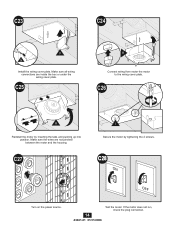
... sure the wires are inside the box or under the wiring cover plate.
If the motor does not run, check the plug connection. C23
C24
F G
Install the wiring cover plate.
C25
H
Connect wiring from motor the motor to the wiring cover plate. C27
I
Secure the motor by inserting the tabs and...
Owner's Manual - Page 15

D14
2 1
Pull wires through strain relief.
accessible only from below
D11 EXISTING FAN
D12
E
Remove an existing fan and check to make sure the opening is large enough to duct connector. Attach existing ducting to accommodate the new motor housing (8"x
8.5"). Existing Construction - If ...
Owner's Manual - Page 16

... from the motor to the wiring cover plate.
16
43041-01 01/31/2008 D16
Fan Motor
F
Light
Black 2 Pin
White
White
3 Pin Black Light *Option
*Option Fan & Main Light Together
Ground Green
A
Bare Copper Black Main Switch 1 (AC In)
White
Black Switch 2 (AC In)
Connect wires as shown. D17
D18
F G
Install the wiring cover plate.
Owner's Manual - Page 18

... wiring harness. E4
J
Position the strain relief bracket under the motor as shown. Align posts A, B, C and D (stamped into motor housing) with
posts A, B, C and D (stamped into light fixture). E6
Insert the strain relief bracket's dog-leg tab so that it hooks over posts.
43041-01 01/31/2008 Slide...
Owner's Manual - Page 19

E9
Install 2 Max 60 Watt A15 bulbs (Not Included). E7
E8
M
Attach thumbscrews.
E10
N
Align glass dome and push up
E11
O
Screw Finial into position
Complete.
19
43041-01 01/31/2008 WARNING: To reduce the risk of electrical shock,
all 4 thumbscrews MUST be properly installed.
Owner's Manual - Page 20

... make sure it matches the wiring diagram. Solution: • Check and tighten all plug connections to make sure it matches the wiring diagram. Solution:
• Hunter Fan Bath Ventilators are secure. • Check the wiring to be sure they are extremely quiet. Trouble Shooting
Problem: Fan does not come on .
Owner's Manual - Page 21

... consumer purchaser of this Hunter bath exhaust fan:
If any part of your Hunter bath exhaust fan (except for glass fixtures and light bulbs) fails at any time within five years after the date of sale to you will be responsible for all parts and labor costs for repairs on the bath exhaust fan except for parts and labor performed at our nearest service center or at...
Hunter 81021 Reviews
We have not received any reviews for Hunter yet.