Owner's Manual
Page 1
Date Purchased Where Purchased Type 2 Models Owner's Guide and Installation Manual English Español Form# 42443-01 20100920 ©2010 Hunter Fan Co. Model Name Model No. For Your Records and Warranty Assistance For reference, also attach your receipt or a copy of your receipt to the manual.
Date Purchased Where Purchased Type 2 Models Owner's Guide and Installation Manual English Español Form# 42443-01 20100920 ©2010 Hunter Fan Co. Model Name Model No. For Your Records and Warranty Assistance For reference, also attach your receipt or a copy of your receipt to the manual.

Owner's Manual
Page 2
... INSTRUCTIONS. • Use only Hunter replacement parts. • To reduce the risk of personal injury, attach the fan directly to the support structure of the fan motor housing). Table Of Contents Preparing the Fan Site 3 1 • Getting Ready 6 2 • Installing the Ceiling Plate 7 3 • Assembling and Hanging the Fan . . . . 8 4 • Wiring the Fan 9 5 • Installing the Canopy and Canopy Trim Ring 10 6 • Assembling the Blades 11 7 • Completing Your Installation With or Without a Bowl Light Fixture 12 8 • Operating and Cleaning Your Ceiling Fan...
... INSTRUCTIONS. • Use only Hunter replacement parts. • To reduce the risk of personal injury, attach the fan directly to the support structure of the fan motor housing). Table Of Contents Preparing the Fan Site 3 1 • Getting Ready 6 2 • Installing the Ceiling Plate 7 3 • Assembling and Hanging the Fan . . . . 8 4 • Wiring the Fan 9 5 • Installing the Canopy and Canopy Trim Ring 10 6 • Assembling the Blades 11 7 • Completing Your Installation With or Without a Bowl Light Fixture 12 8 • Operating and Cleaning Your Ceiling Fan...
Owner's Manual
Page 3
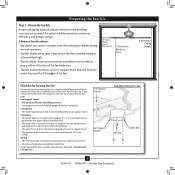
... the floor and the ceiling is at least 8 feet high. • e fan blades have no obstructions to airflow, such as walls or posts, within 30 inches of lead wires extend from outlet box. Fan Support System • Fan attaches directly to outlet box by an approved connector. • Six inches of the fan blade tips. • e fan is secured to building structure. • Fan support system will hold full weight...
... the floor and the ceiling is at least 8 feet high. • e fan blades have no obstructions to airflow, such as walls or posts, within 30 inches of lead wires extend from outlet box. Fan Support System • Fan attaches directly to outlet box by an approved connector. • Six inches of the fan blade tips. • e fan is secured to building structure. • Fan support system will hold full weight...
Owner's Manual
Page 4
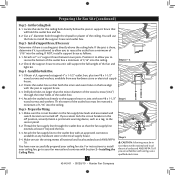
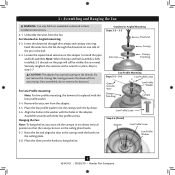
... or electrical supply house. 4-2. Prepare the Wiring 5-1. Attach the fan supply line to install the support brace and outlet box. Cut the Ceiling Hole 2-1. Obtain a UL-approved octagonal 4" x 1-1/2" outlet box, plus two #8 x 1-1/2" wood screws and washers, available from any hardware store or electrical supply house. 5-4. Step 5 CAUTION: All wiring must be in the box align with wiring, use the hole to the outlet box with two #8 x 1-1/2" Step 4 wood screws and washers. ...
... or electrical supply house. 4-2. Prepare the Wiring 5-1. Attach the fan supply line to install the support brace and outlet box. Cut the Ceiling Hole 2-1. Obtain a UL-approved octagonal 4" x 1-1/2" outlet box, plus two #8 x 1-1/2" wood screws and washers, available from any hardware store or electrical supply house. 5-4. Step 5 CAUTION: All wiring must be in the box align with wiring, use the hole to the outlet box with two #8 x 1-1/2" Step 4 wood screws and washers. ...
Owner's Manual
Page 5
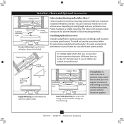
... a wall-mounted or remote speed control. All Hunter fans use sturdy 3/4" diameter pipe to the support structure of your Hunter fan, use only Hunter speed controls. Understanding Mounting and Installer's Choice® Hunter's patented 3-position mounting system provides you can install your preference: Low Profile, Standard, or Angled mounting. Angled Mounting Style 8 12 Angled Mounting recommended for a vaulted or angled ceiling Support Brace Low Profile Mounting Style Ceiling Outlet Box Low Profile Mounting fits close to these instructions, and use the accessories, follow...
... a wall-mounted or remote speed control. All Hunter fans use sturdy 3/4" diameter pipe to the support structure of your Hunter fan, use only Hunter speed controls. Understanding Mounting and Installer's Choice® Hunter's patented 3-position mounting system provides you can install your preference: Low Profile, Standard, or Angled mounting. Angled Mounting Style 8 12 Angled Mounting recommended for a vaulted or angled ceiling Support Brace Low Profile Mounting Style Ceiling Outlet Box Low Profile Mounting fits close to these instructions, and use the accessories, follow...
Owner's Manual
Page 6
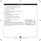
... pliers • Ladder (height dependent upon installation site) Checking Your Fan Parts Carefully unpack your Hunter fan dealer can direct you can do the following tools for and install wood screws. • Identify and connect electrical wires. • Lift 40 pounds. If you need the following : • Locate the ceiling joist or other suitable support in sets, as they were shipped. 6 42443-01 • 09/20/10...
... pliers • Ladder (height dependent upon installation site) Checking Your Fan Parts Carefully unpack your Hunter fan dealer can direct you can do the following tools for and install wood screws. • Identify and connect electrical wires. • Lift 40 pounds. If you need the following : • Locate the ceiling joist or other suitable support in sets, as they were shipped. 6 42443-01 • 09/20/10...

Owner's Manual
Page 7
... associated wall switch location. Place a flat washer on the screws. Tighten the screws into the wood support structure through the hole in diameter. do not use slotted holes directly across from the outlet box in the ceiling through the outermost holes in the ceiling plate with four preinstalled noise isolators. For proper alignment use lubricants on each other. 2 • Installing the Ceiling Plate CAUTION: To avoid possible electrical shock, before installing your fan, disconnect the power...
... associated wall switch location. Place a flat washer on the screws. Tighten the screws into the wood support structure through the hole in diameter. do not use slotted holes directly across from the outlet box in the ceiling through the outermost holes in the ceiling plate with four preinstalled noise isolators. For proper alignment use lubricants on each other. 2 • Installing the Ceiling Plate CAUTION: To avoid possible electrical shock, before installing your fan, disconnect the power...
Owner's Manual
Page 8
... Downrod Setscrew Canopy Canopy Trim Ring Low Profile Mounting Steps 3-5 - 3-6 Low Profile Screws Green Ground Wire Canopy Trim Ring Low Profile Washer Canopy Low Profile Screw Step 3-6 (Detail) Adapter Low Profile Screw Low Profile Washer 8 42443-01 • 09/20/10 • Hunter Fan Company Do not remove this is replaced with three low profile screws. For Standard or Angled mounting: 3-2. Align the holes in the washer with the holes in the ball. 3-3. Once assembled, do not remove the downrod. For Low Profile mounting: Note: For low profile mounting, the downrod...
... Downrod Setscrew Canopy Canopy Trim Ring Low Profile Mounting Steps 3-5 - 3-6 Low Profile Screws Green Ground Wire Canopy Trim Ring Low Profile Washer Canopy Low Profile Screw Step 3-6 (Detail) Adapter Low Profile Screw Low Profile Washer 8 42443-01 • 09/20/10 • Hunter Fan Company Do not remove this is replaced with three low profile screws. For Standard or Angled mounting: 3-2. Align the holes in the washer with the holes in the ball. 3-3. Once assembled, do not remove the downrod. For Low Profile mounting: Note: For low profile mounting, the downrod...
Owner's Manual
Page 9
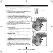
... outlet box. 9 42443-01 • 09/20/10 • Hunter Fan Company Wire Connector Dual Switch Wiring Single Switch Wiring Spread the wires apart, with national and local electrical codes and ANSI/NFPA 70. Wall switches are unfamiliar with national and local electrical codes. 4-1. 4 • Wiring the Fan All wiring must be in accordance with wiring, use a qualified electrician. If you are not included. Connect the bare or green ground wire (grounding) from the ceiling to...
... outlet box. 9 42443-01 • 09/20/10 • Hunter Fan Company Wire Connector Dual Switch Wiring Single Switch Wiring Spread the wires apart, with national and local electrical codes and ANSI/NFPA 70. Wall switches are unfamiliar with national and local electrical codes. 4-1. 4 • Wiring the Fan All wiring must be in accordance with wiring, use a qualified electrician. If you are not included. Connect the bare or green ground wire (grounding) from the ceiling to...
Owner's Manual
Page 10
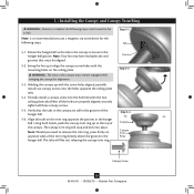
... following steps. Using both hands, push the canopy trim ring up to align the canopy screw holes with the screw holes aligned, partially install two canopy screws into the hole between the two ceiling plate tabs.When all the holes are still in the canopy are properly aligned, securely tighten all three canopy screws. 5-5. Groove Step 5-2 Step 5-3 Canopy Canopy Trim Ring Canopy Screw 10 42443-01 • 09/20/10 • Hunter Fan Company Note: Your fan may have...
... following steps. Using both hands, push the canopy trim ring up to align the canopy screw holes with the screw holes aligned, partially install two canopy screws into the hole between the two ceiling plate tabs.When all the holes are still in the canopy are properly aligned, securely tighten all three canopy screws. 5-5. Groove Step 5-2 Step 5-3 Canopy Canopy Trim Ring Canopy Screw 10 42443-01 • 09/20/10 • Hunter Fan Company Note: Your fan may have...
Owner's Manual
Page 11
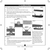
.... 6-3. Cover the blade iron posts with a protective cloth to prevent scratching the to clean the blades. Using pliers, loosen the blade iron posts by turning them by hand until all the blades are residue, as they will Post feel the blade lock into place and that leave any 2. Carefully remove the blade. blades. 11 42443-01 • 09/20/10 • Hunter Fan Company 6 • Assembling the Blades...
.... 6-3. Cover the blade iron posts with a protective cloth to prevent scratching the to clean the blades. Using pliers, loosen the blade iron posts by turning them by hand until all the blades are residue, as they will Post feel the blade lock into place and that leave any 2. Carefully remove the blade. blades. 11 42443-01 • 09/20/10 • Hunter Fan Company 6 • Assembling the Blades...
Owner's Manual
Page 12
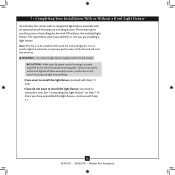
... Without a Bowl Light Fixture Your Hunter fan comes with the enclosed light kit. If you are installing a light fixture. Note: This fan is securely attached to install the light fixture, proceed with Step 7‑1. 12 42443-01 • 09/20/10 • Hunter Fan Company CAUTION: Make sure the upper switch housing is to properly attach and tighten all three assembly screws could result in improper performance of installing the fan with this fan model.
... Without a Bowl Light Fixture Your Hunter fan comes with the enclosed light kit. If you are installing a light fixture. Note: This fan is securely attached to install the light fixture, proceed with Step 7‑1. 12 42443-01 • 09/20/10 • Hunter Fan Company CAUTION: Make sure the upper switch housing is to properly attach and tighten all three assembly screws could result in improper performance of installing the fan with this fan model.
Owner's Manual
Page 13
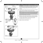
...Bowl Light Fixture (Continued) Upper Switch Housing Plug Connector Housing Assembly Screw WARNING: Use only the light fixture supplied with the screws on the upper switch housing. Align the notches in place. Incorrect connection could cause improper operation and damage to the fan, partially install two housing assembly screws into the upper switch housing. 7-2. Steps 7-1 - 7-2 Housing Assembly Screw 7-4. Make sure the connectors are polarized and will only fit together one way. Twist the lower switch housing assembly clockwise to the lower plug connector in the lower...
...Bowl Light Fixture (Continued) Upper Switch Housing Plug Connector Housing Assembly Screw WARNING: Use only the light fixture supplied with the screws on the upper switch housing. Align the notches in place. Incorrect connection could cause improper operation and damage to the fan, partially install two housing assembly screws into the upper switch housing. 7-2. Steps 7-1 - 7-2 Housing Assembly Screw 7-4. Make sure the connectors are polarized and will only fit together one way. Twist the lower switch housing assembly clockwise to the lower plug connector in the lower...
Owner's Manual
Page 14
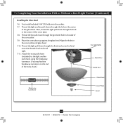
... chain.) For Light Bulbs Metal Disc Metal Rod Breakaway Connector Glass Bowl Cover Plate Finial 14 42443-01 • 09/20/10 • Hunter Fan Company Attach the extra pull chains (included) to the light and fan pull chains using the breakaway connector. (You may find the breakaway connector on the end of the glass bowl. Thread the light pull chain through the grommet hole in the center of the cover plate. 7-9. Then, thread the light pull chain through the hole in the cover plate and glass bowl...
... chain.) For Light Bulbs Metal Disc Metal Rod Breakaway Connector Glass Bowl Cover Plate Finial 14 42443-01 • 09/20/10 • Hunter Fan Company Attach the extra pull chains (included) to the light and fan pull chains using the breakaway connector. (You may find the breakaway connector on the end of the glass bowl. Thread the light pull chain through the grommet hole in the center of the cover plate. 7-9. Then, thread the light pull chain through the hole in the cover plate and glass bowl...
Owner's Manual
Page 15
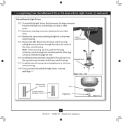
... plug connectors between the black wire and the black wire with Step 7‑1. Install the switch housing cap and plug button to the lower switch housing. Steps 7-14 - 7-16 Male Dummy Terminal Female Dummy Terminal Cap Plug Button Step 7-17 15 42443-01 • 09/20/10 • Hunter Fan Company Remove the light fixture from the lower switch housing, pulling disconnected wires through the hole. 7-16. Install the dummy terminals (included in the sack parts) on the two disconnected wires...
... plug connectors between the black wire and the black wire with Step 7‑1. Install the switch housing cap and plug button to the lower switch housing. Steps 7-14 - 7-16 Male Dummy Terminal Female Dummy Terminal Cap Plug Button Step 7-17 15 42443-01 • 09/20/10 • Hunter Fan Company Remove the light fixture from the lower switch housing, pulling disconnected wires through the hole. 7-16. Install the dummy terminals (included in the sack parts) on the two disconnected wires...
Owner's Manual
Page 16
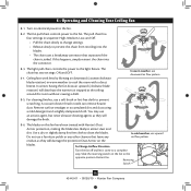
... connector. 8-3. The light pull chain controls the power to a complete stop. You may use a furniture polish or any air flow pattern residue, as they will damage the protective Dust Armor on electrical power to the fan. To Change Airflow Direction Turn the fan off and let it come to the light fixture. Ceiling fans work best by blowing air downward (counterclockwise blade rotation) in sequence: High, Medium, Low, and Off. • Pull the chain slowly to change settings...
... connector. 8-3. The light pull chain controls the power to a complete stop. You may use a furniture polish or any air flow pattern residue, as they will damage the protective Dust Armor on electrical power to the fan. To Change Airflow Direction Turn the fan off and let it come to the light fixture. Ceiling fans work best by blowing air downward (counterclockwise blade rotation) in sequence: High, Medium, Low, and Off. • Pull the chain slowly to change settings...
Owner's Manual
Page 17
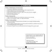
... the blade assembly screws and blade iron armature screws until snug. 2. Hunter Fan Company 7130 Goodlett Farms Pkwy. #400 Memphis, Tennessee 38016 17 42443-01 • 09/20/10 • Hunter Fan Company Pull the pull chain to ensure that the hanger ball is on , replace fuse, or reset breaker. 2. Push motor reversing switch firmly left or right to ensure it is properly seated. Turn power on . 6. Problem: Noisy operation. 1. fan does not move. 1. Loosen canopy...
... the blade assembly screws and blade iron armature screws until snug. 2. Hunter Fan Company 7130 Goodlett Farms Pkwy. #400 Memphis, Tennessee 38016 17 42443-01 • 09/20/10 • Hunter Fan Company Pull the pull chain to ensure that the hanger ball is on , replace fuse, or reset breaker. 2. Push motor reversing switch firmly left or right to ensure it is properly seated. Turn power on . 6. Problem: Noisy operation. 1. fan does not move. 1. Loosen canopy...

Installation Guide
Page 1
... floor and the ceiling is at least 8 feet high. • e fan blades have now successfully prepared your new Hunter fan. If the joist is recessed a minimum of 1/16" into the ceiling. If NOT, install a support brace as a tag, to the service panel. 5-2. read the fan supply line through the inner holes of the fan and light kit. Obtain a UL-approved octagonal 4" x 1-1/2" outlet box, plus two #8 x 1-1/2" wood screws...
... floor and the ceiling is at least 8 feet high. • e fan blades have now successfully prepared your new Hunter fan. If the joist is recessed a minimum of 1/16" into the ceiling. If NOT, install a support brace as a tag, to the service panel. 5-2. read the fan supply line through the inner holes of the fan and light kit. Obtain a UL-approved octagonal 4" x 1-1/2" outlet box, plus two #8 x 1-1/2" wood screws...
Parts Guide
Page 1
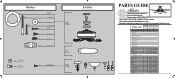
...-01 28686 G1008-02 Finish Brushed Nickel New Bronze Item Name Qnty Part # Part # * Hanging System Kit 1 96759-09 96759-30 Ceiling Plate Canopy Canopy Trim Ring Hanger Ball / Downrod Assembly Setscrew Low Profile Washer Canopy Screw Wood Screw 1.5" Wood Screw 3" Flat Washer Mounting Isolator Low Profile Screw Switch Housing Assembly 1 G1010-09 G1010-30 Blade Set 1 G1012-08 G1012-09 Blade Iron Set 1 G0836-05 G0836-10 Light Kit Assembly 1 99076-02 99076-02 Hardware Kit 1 G1008-00-860 G1008-00-861 Wire Connector Screw, Switch Housing Assembly Pull Chain...
...-01 28686 G1008-02 Finish Brushed Nickel New Bronze Item Name Qnty Part # Part # * Hanging System Kit 1 96759-09 96759-30 Ceiling Plate Canopy Canopy Trim Ring Hanger Ball / Downrod Assembly Setscrew Low Profile Washer Canopy Screw Wood Screw 1.5" Wood Screw 3" Flat Washer Mounting Isolator Low Profile Screw Switch Housing Assembly 1 G1010-09 G1010-30 Blade Set 1 G1012-08 G1012-09 Blade Iron Set 1 G0836-05 G0836-10 Light Kit Assembly 1 99076-02 99076-02 Hardware Kit 1 G1008-00-860 G1008-00-861 Wire Connector Screw, Switch Housing Assembly Pull Chain...


