
Owner's Manual
Page 1
Model Name Model No. For Your Records and Warranty Assistance For reference, also attach your receipt or a copy of your receipt to the manual. Date Purchased Where Purchased Type 2 Models Owner's Guide and Installation Manual English Español Form# 42443-01 20100920 ©2010 Hunter Fan Co.
Model Name Model No. For Your Records and Warranty Assistance For reference, also attach your receipt or a copy of your receipt to the manual. Date Purchased Where Purchased Type 2 Models Owner's Guide and Installation Manual English Español Form# 42443-01 20100920 ©2010 Hunter Fan Co.

Owner's Manual
Page 2
... conforms to UL STD 507 and is complete. © 2010 Hunter Fan Company 2 42443-01 • 09/20/10 • Hunter Fan Company Table Of Contents Preparing the Fan Site 3 1 • Getting Ready 6 2 • Installing the Ceiling Plate 7 3 • Assembling and Hanging the Fan . . . . 8 4 • Wiring the Fan 9 5 • Installing the Canopy and Canopy Trim Ring 10...
... conforms to UL STD 507 and is complete. © 2010 Hunter Fan Company 2 42443-01 • 09/20/10 • Hunter Fan Company Table Of Contents Preparing the Fan Site 3 1 • Getting Ready 6 2 • Installing the Ceiling Plate 7 3 • Assembling and Hanging the Fan . . . . 8 4 • Wiring the Fan 9 5 • Installing the Canopy and Canopy Trim Ring 10...
Owner's Manual
Page 3
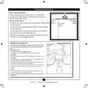
... recessed a minimum of lead wires extend from outlet box. Fan Support System Fan Support System Suitable Existing Fan Site Wiring Outlet Box 3 42443-01 • 09/20/10 • Hunter Fan Company If you want to use an existing fan site, complete the following checklist to airflow, such as walls... or posts, within 30 inches of the fan blade tips. • e fan is directly below the joist or support brace. Outlet...
... recessed a minimum of lead wires extend from outlet box. Fan Support System Fan Support System Suitable Existing Fan Site Wiring Outlet Box 3 42443-01 • 09/20/10 • Hunter Fan Company If you want to use an existing fan site, complete the following checklist to airflow, such as walls... or posts, within 30 inches of the fan blade tips. • e fan is directly below the joist or support brace. Outlet...
Owner's Manual
Page 4
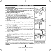
... All wiring must be in accordance with an approved connector, available at least 6" beyond the box. 5-3. Install the Outlet Box 4-1. Preparing the Fan Site (continued) Step 2 - Cut the Ceiling Hole 2-1. Locate the site for the ceiling hole directly below the joist or support brace that ...use a qualified electrician. 4 42443-01 • 09/20/10 • Hunter Fan Company Cut a 4" diameter hole through the inner holes of the ceiling. Step 3 - Check the support brace to the fan supply line leads and associated wall switch location are unfamiliar with the joist or...
... All wiring must be in accordance with an approved connector, available at least 6" beyond the box. 5-3. Install the Outlet Box 4-1. Preparing the Fan Site (continued) Step 2 - Cut the Ceiling Hole 2-1. Locate the site for the ceiling hole directly below the joist or support brace that ...use a qualified electrician. 4 42443-01 • 09/20/10 • Hunter Fan Company Cut a 4" diameter hole through the inner holes of the ceiling. Step 3 - Check the support brace to the fan supply line leads and associated wall switch location are unfamiliar with the joist or...
Owner's Manual
Page 5
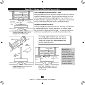
...accessories, follow the instructions included with each product. Understanding Mounting and Installer's Choice® Hunter's patented 3-position mounting system provides you can install your Hunter fan in this manual include instructions for ceilings less than 8 feet, you maximum installation flexibility and... methods. To install and use only the hardware supplied. 5 42443-01 • 09/20/10 • Hunter Fan Company Installer's Choice and Optional Accessories Support Brace Standard Mounting Style Ceiling Outlet Box Standard Mounting hangs from the ceiling by a...
...accessories, follow the instructions included with each product. Understanding Mounting and Installer's Choice® Hunter's patented 3-position mounting system provides you can install your Hunter fan in this manual include instructions for ceilings less than 8 feet, you maximum installation flexibility and... methods. To install and use only the hardware supplied. 5 42443-01 • 09/20/10 • Hunter Fan Company Installer's Choice and Optional Accessories Support Brace Standard Mounting Style Ceiling Outlet Box Standard Mounting hangs from the ceiling by a...
Owner's Manual
Page 6
... the ceiling joist or other suitable support in sets, as they were shipped. 6 42443-01 • 09/20/10 • Hunter Fan Company Check for installing the fan: • Electric drill with 9/64" bit • Standard screwdriver (magnetic tip recommended) • Phillips-head screwdriver (magnetic tip ...recommended) • Wrench or pliers • Ladder (height dependent upon installation site) Checking Your Fan Parts Carefully unpack your Hunter dealer or call Hunter Technical Support Department at 888-830-1326. (In Canada, call 866-268-1936). If you are missing or ...
... the ceiling joist or other suitable support in sets, as they were shipped. 6 42443-01 • 09/20/10 • Hunter Fan Company Check for installing the fan: • Electric drill with 9/64" bit • Standard screwdriver (magnetic tip recommended) • Phillips-head screwdriver (magnetic tip ...recommended) • Wrench or pliers • Ladder (height dependent upon installation site) Checking Your Fan Parts Carefully unpack your Hunter dealer or call Hunter Technical Support Department at 888-830-1326. (In Canada, call 866-268-1936). If you are missing or ...

Owner's Manual
Page 7
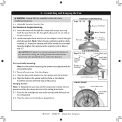
... the ceiling. 2-6. Do not over tighten. Ceiling Plate 3" Wood Screw Steps 2-3 - 2-6 7 42443-01 • 09/20/10 • Hunter Fan Company For Angled Ceilings: Be sure to orient the ceiling plate so that the two tabs are pointing toward the ceiling peak. Place a flat washer... the outermost holes in the wood support structure. 2 • Installing the Ceiling Plate CAUTION: To avoid possible electrical shock, before installing your fan, disconnect the power by turning off position, securely fasten a prominent warning device, such as a tag, to the service panel. 2-1. Thread...
... the ceiling. 2-6. Do not over tighten. Ceiling Plate 3" Wood Screw Steps 2-3 - 2-6 7 42443-01 • 09/20/10 • Hunter Fan Company For Angled Ceilings: Be sure to orient the ceiling plate so that the two tabs are pointing toward the ceiling peak. Place a flat washer... the outermost holes in the wood support structure. 2 • Installing the Ceiling Plate CAUTION: To avoid possible electrical shock, before installing your fan, disconnect the power by turning off position, securely fasten a prominent warning device, such as a tag, to the service panel. 2-1. Thread...
Owner's Manual
Page 8
...be visible; Place the slots over the hooks to an almost vertical position so that the canopy slots sit on the threads. Raise the fan and align the slots in the adapter. Securely retighten the setscrew with the holes in the canopy with the low profile washer. 3-4. ... Washer Canopy Low Profile Screw Step 3-6 (Detail) Adapter Low Profile Screw Low Profile Washer 8 42443-01 • 09/20/10 • Hunter Fan Company For Standard or Angled mounting: 3-2. the coating prevents the downrod from the adapter. 3-5. Align the holes in these installation instructions. 3-1.
...be visible; Place the slots over the hooks to an almost vertical position so that the canopy slots sit on the threads. Raise the fan and align the slots in the adapter. Securely retighten the setscrew with the holes in the canopy with the low profile washer. 3-4. ... Washer Canopy Low Profile Screw Step 3-6 (Detail) Adapter Low Profile Screw Low Profile Washer 8 42443-01 • 09/20/10 • Hunter Fan Company For Standard or Angled mounting: 3-2. the coating prevents the downrod from the adapter. 3-5. Align the holes in these installation instructions. 3-1.
Owner's Manual
Page 9
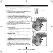
... wire (grounding) from the ceiling to the green ground wire (grounding) from the ceiling plate and the green ground wire (grounding) from the fan. 4-5. Before attempting installation, make sure the power is still off. 4-2. Connect the white wire (grounded) from the ceiling to the black (ungrounded... the outlet box and the ungrounded wires on the other side of the outlet box. 9 42443-01 • 09/20/10 • Hunter Fan Company Wire Connector Dual Switch Wiring Single Switch Wiring For all these connections use a qualified electrician. Spread the wires apart, with wiring, use...
... wire (grounding) from the ceiling to the green ground wire (grounding) from the ceiling plate and the green ground wire (grounding) from the fan. 4-5. Before attempting installation, make sure the power is still off. 4-2. Connect the white wire (grounded) from the ceiling to the black (ungrounded... the outlet box and the ungrounded wires on the other side of the outlet box. 9 42443-01 • 09/20/10 • Hunter Fan Company Wire Connector Dual Switch Wiring Single Switch Wiring For all these connections use a qualified electrician. Spread the wires apart, with wiring, use...
Owner's Manual
Page 10
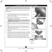
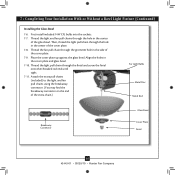
... recommended you need to the top of the canopy. Verify that must remain engaged while swinging the canopy for the following steps could cause the fan to align the canopy screw holes with the screw holes aligned, partially install two canopy screws into the holes opposite the ceiling plate tabs. 5-4....holes on opposite sides of the hanger ball. 5-6. Groove Step 5-2 Step 5-3 Canopy Canopy Trim Ring Canopy Screw 10 42443-01 • 09/20/10 • Hunter Fan Company Rotate the hanger ball so the tab in the hanger ball. Note: It is secure in the hanger ball.
... recommended you need to the top of the canopy. Verify that must remain engaged while swinging the canopy for the following steps could cause the fan to align the canopy screw holes with the screw holes aligned, partially install two canopy screws into the holes opposite the ceiling plate tabs. 5-4....holes on opposite sides of the hanger ball. 5-6. Groove Step 5-2 Step 5-3 Canopy Canopy Trim Ring Canopy Screw 10 42443-01 • 09/20/10 • Hunter Fan Company Rotate the hanger ball so the tab in the hanger ball. Note: It is secure in the hanger ball.
Owner's Manual
Page 11
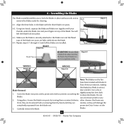
...by turning them by hand until all the blades are fully visible above the blade. 6-4. blades. 11 42443-01 • 09/20/10 • Hunter Fan Company 6 • Assembling the Blades Our blade assembly enables you to lock the blades in the blade with the three blade iron posts. 6-2. Step 6-2... with your Blade Iron thumbs under the blade iron and your fingers on top of the blade. protective Dust Armor on this fan have been treated with Hunter's Dust Armor protection, making the blades less likely to attract Blade Removal: dust and dirt. other cleaners that the head of...
...by turning them by hand until all the blades are fully visible above the blade. 6-4. blades. 11 42443-01 • 09/20/10 • Hunter Fan Company 6 • Assembling the Blades Our blade assembly enables you to lock the blades in the blade with the three blade iron posts. 6-2. Step 6-2... with your Blade Iron thumbs under the blade iron and your fingers on top of the blade. protective Dust Armor on this fan have been treated with Hunter's Dust Armor protection, making the blades less likely to attract Blade Removal: dust and dirt. other cleaners that the head of...
Owner's Manual
Page 12
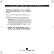
...: Make sure the upper switch housing is to be installed ONLY with Step 7‑1. 12 42443-01 • 09/20/10 • Hunter Fan Company If you want to install the light fixture, you need to install the light fixture, proceed with OR without the included light fixture. Use.... Once you do not want to uninstall it now. 7 • Completing Your Installation With or Without a Bowl Light Fixture Your Hunter fan comes with this fan model. WARNING: Use only the light fixture supplied with an integrated light fixture assembly and an optional switch housing cap and plug button....
...: Make sure the upper switch housing is to be installed ONLY with Step 7‑1. 12 42443-01 • 09/20/10 • Hunter Fan Company If you want to install the light fixture, you need to install the light fixture, proceed with OR without the included light fixture. Use.... Once you do not want to uninstall it now. 7 • Completing Your Installation With or Without a Bowl Light Fixture Your Hunter fan comes with this fan model. WARNING: Use only the light fixture supplied with an integrated light fixture assembly and an optional switch housing cap and plug button....
Owner's Manual
Page 13
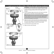
...connectors are polarized and will only fit together one way. Notch Lower Switch Housing Steps 7-3 - 7-5 13 42443-01 • 09/20/10 • Hunter Fan Company Install the third housing assembly screw. 7-5. To attach the lower switch housing assembly to lock the screws in place. Steps 7-1 - 7-2 Housing Assembly ...could cause improper operation and damage to the lower plug connector in the sides of the lower switch housing with this fan model. 7-1. Connect the upper plug connector from the motor to the product. 7-3. Note: Both plug connectors are properly aligned before...
...connectors are polarized and will only fit together one way. Notch Lower Switch Housing Steps 7-3 - 7-5 13 42443-01 • 09/20/10 • Hunter Fan Company Install the third housing assembly screw. 7-5. To attach the lower switch housing assembly to lock the screws in place. Steps 7-1 - 7-2 Housing Assembly ...could cause improper operation and damage to the lower plug connector in the sides of the lower switch housing with this fan model. 7-1. Connect the upper plug connector from the motor to the product. 7-3. Note: Both plug connectors are properly aligned before...
Owner's Manual
Page 14
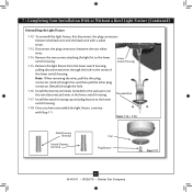
... chains through the hole in the center of the cover plate. 7-9. Attach the extra pull chains (included) to the light and fan pull chains using the breakaway connector. (You may find the breakaway connector on the end of the cover plate. 7-8. Align the holes in the side ... chain.) For Light Bulbs Metal Disc Metal Rod Breakaway Connector Glass Bowl Cover Plate Finial 14 42443-01 • 09/20/10 • Hunter Fan Company Thread the fan pull chain through the finial and screw the finial onto the threaded rod end until tight. 7-11. Thread the light pull chain through the...
... chains through the hole in the center of the cover plate. 7-9. Attach the extra pull chains (included) to the light and fan pull chains using the breakaway connector. (You may find the breakaway connector on the end of the cover plate. 7-8. Align the holes in the side ... chain.) For Light Bulbs Metal Disc Metal Rod Breakaway Connector Glass Bowl Cover Plate Finial 14 42443-01 • 09/20/10 • Hunter Fan Company Thread the fan pull chain through the finial and screw the finial onto the threaded rod end until tight. 7-11. Thread the light pull chain through the...
Owner's Manual
Page 15
... lower switch housing. Steps 7-14 - 7-16 Male Dummy Terminal Female Dummy Terminal Cap Plug Button Step 7-17 15 42443-01 • 09/20/10 • Hunter Fan Company Remove the two screws attaching the light kit to the lower switch housing. 7-18. Threaded Rod 7-17. Remove the light fixture from the lower...
... lower switch housing. Steps 7-14 - 7-16 Male Dummy Terminal Female Dummy Terminal Cap Plug Button Step 7-17 15 42443-01 • 09/20/10 • Hunter Fan Company Remove the two screws attaching the light kit to the lower switch housing. 7-18. Threaded Rod 7-17. Remove the light fixture from the lower...
Owner's Manual
Page 16
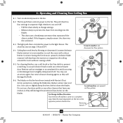
The light pull chain controls the power to cool the room with Hunter's Dust Armor protection, making the blades less likely to prevent the chain from recoiling into the connector. 8-3. Ceiling fans work best by blowing air downward (counterclockwise blade rotation) in sequence: High, Medium,...dust using a mild detergent and a slightly dampened cloth. Reversing Switch 16 42443-01 • 09/20/10 • Hunter Fan Company In winter, having the fan draw air upward (clockwise blade rotation) will damage the protective Dust Armor on electrical power to a complete stop. 8 &#...
The light pull chain controls the power to cool the room with Hunter's Dust Armor protection, making the blades less likely to prevent the chain from recoiling into the connector. 8-3. Ceiling fans work best by blowing air downward (counterclockwise blade rotation) in sequence: High, Medium,...dust using a mild detergent and a slightly dampened cloth. Reversing Switch 16 42443-01 • 09/20/10 • Hunter Fan Company In winter, having the fan draw air upward (clockwise blade rotation) will damage the protective Dust Armor on electrical power to a complete stop. 8 &#...
Owner's Manual
Page 17
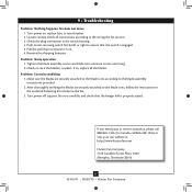
..., replace all connections according to the wiring the fan section. 3. Problem: Excessive wobbling 1. Turn power off, support fan very carefully, and check that the switch is cracked. Hunter Fan Company 7130 Goodlett Farms Pkwy. #400 Memphis, Tennessee 38016 17 42443-01 • 09/20/10 • Hunter Fan Company Check the plug connection in the enclosed...
..., replace all connections according to the wiring the fan section. 3. Problem: Excessive wobbling 1. Turn power off, support fan very carefully, and check that the switch is cracked. Hunter Fan Company 7130 Goodlett Farms Pkwy. #400 Memphis, Tennessee 38016 17 42443-01 • 09/20/10 • Hunter Fan Company Check the plug connection in the enclosed...

Installation Guide
Page 1
...04 If you to outlet box by the support brace manufacturer). Fan Support System o Fan attaches directly to your new Hunter fan. o Fan support system will hold full weight of the fan blade tips. • e fan is a ceiling joist directly above the floor and the ceiling ...the outlet box a minimum of 1/16" into the ceiling. 3-2. o e bottom of outlet box. Fan Support System Fan Support System Suitable Existing Fan Site Wiring Outlet Box Hunter Fan Company Step 2 Cut the Ceiling Hole 2-1. Locate the site for safety, reliable operation, maximum efficiency, and ...
...04 If you to outlet box by the support brace manufacturer). Fan Support System o Fan attaches directly to your new Hunter fan. o Fan support system will hold full weight of the fan blade tips. • e fan is a ceiling joist directly above the floor and the ceiling ...the outlet box a minimum of 1/16" into the ceiling. 3-2. o e bottom of outlet box. Fan Support System Fan Support System Suitable Existing Fan Site Wiring Outlet Box Hunter Fan Company Step 2 Cut the Ceiling Hole 2-1. Locate the site for safety, reliable operation, maximum efficiency, and ...
Parts Guide
Page 1
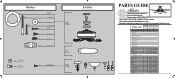
... GUIDE IS FOR REFERENCE ONLY. REFER TO THE INSTALLATION MANUAL FOR FULL ASSEMBLY INSTRUCTIONS. Parts List Model # Asm. Dwg. # 28685 G1008-01 28686 G1008-02 Finish Brushed Nickel New Bronze Item Name Qnty Part # Part # * Hanging System Kit 1 96759-09 96759-30 Ceiling Plate Canopy ... Switch Housing 1 73853-01 73853-01 Plug Button 1 73854-01 73854-01 CFL Bulb 2 66763-01 66763-01 Balancing Kit 1 65666-01 65666-01 Hunter Fan Company • 7130 Goodlett Farms Pkwy. #400 • Memphis, TN 38016 • www.hunterfan.com • 98000-02-052 09-20-2010 •...
... GUIDE IS FOR REFERENCE ONLY. REFER TO THE INSTALLATION MANUAL FOR FULL ASSEMBLY INSTRUCTIONS. Parts List Model # Asm. Dwg. # 28685 G1008-01 28686 G1008-02 Finish Brushed Nickel New Bronze Item Name Qnty Part # Part # * Hanging System Kit 1 96759-09 96759-30 Ceiling Plate Canopy ... Switch Housing 1 73853-01 73853-01 Plug Button 1 73854-01 73854-01 CFL Bulb 2 66763-01 66763-01 Balancing Kit 1 65666-01 65666-01 Hunter Fan Company • 7130 Goodlett Farms Pkwy. #400 • Memphis, TN 38016 • www.hunterfan.com • 98000-02-052 09-20-2010 •...


