
Installation Guide
Page 1
... Fan Support System Suitable Existing Fan Site Wiring Outlet Box Hunter Fan Company Step 2 Cut the Ceiling Hole 2-1. Attach the fan supply line to the outlet box with an approved connector, available at any hardware store or electrical supply house. 4-2. For instructions to install your ceiling fan, go to your fan manual and continue with 2 • Installing the Ceiling Plate. o e outer holes of 1/16" into the ceiling. Cut a 4" diameter hole through the inner holes of the fan and light kit...
... Fan Support System Suitable Existing Fan Site Wiring Outlet Box Hunter Fan Company Step 2 Cut the Ceiling Hole 2-1. Attach the fan supply line to the outlet box with an approved connector, available at any hardware store or electrical supply house. 4-2. For instructions to install your ceiling fan, go to your fan manual and continue with 2 • Installing the Ceiling Plate. o e outer holes of 1/16" into the ceiling. Cut a 4" diameter hole through the inner holes of the fan and light kit...

Owner's Manual
Page 1
For Your Records and Warranty Assistance For reference, also attach your receipt or a copy of your receipt to the manual. Model Name Model No. Date Purchased Where Purchased Type T Models Owner's Guide and Installation Manual English Español Form# 42692-01 20101015 ©2010 Hunter Fan Co.
For Your Records and Warranty Assistance For reference, also attach your receipt or a copy of your receipt to the manual. Model Name Model No. Date Purchased Where Purchased Type T Models Owner's Guide and Installation Manual English Español Form# 42692-01 20101015 ©2010 Hunter Fan Co.

Owner's Manual
Page 2
...; Installing the Ceiling Plate 7 3 • Assembling and Hanging the Fan..........8 4 • Wiring the Fan 9 5 • Installing the Canopy and Canopy Trim Ring 10 6 • Assembling the Blades 11 7 • Installing the Switch Housing 12 8 • Operating and Cleaning Your Ceiling Fan 13 9 • Troubleshooting 15 Cautions and Warnings • READ THIS ENTIRE MANUAL CAREFULLY BEFORE BEGINNING INSTALLATION. Never insert foreign objects between rotating fan blades. • To reduce the risk of personal injury, do not use a solid-state speed control...
...; Installing the Ceiling Plate 7 3 • Assembling and Hanging the Fan..........8 4 • Wiring the Fan 9 5 • Installing the Canopy and Canopy Trim Ring 10 6 • Assembling the Blades 11 7 • Installing the Switch Housing 12 8 • Operating and Cleaning Your Ceiling Fan 13 9 • Troubleshooting 15 Cautions and Warnings • READ THIS ENTIRE MANUAL CAREFULLY BEFORE BEGINNING INSTALLATION. Never insert foreign objects between rotating fan blades. • To reduce the risk of personal injury, do not use a solid-state speed control...
Owner's Manual
Page 3
... savings. Ceiling Hole • The outlet box clearance hole is at least 8 feet high. • The fan blades have no obstructions to the joist or support brace by an approved connector. • Six inches of the fan and light kit. If your existing fan site is acceptable and safe for Existing Fan Site If you cannot check off every item, prepare a new fan site as walls or posts...
... savings. Ceiling Hole • The outlet box clearance hole is at least 8 feet high. • The fan blades have no obstructions to the joist or support brace by an approved connector. • Six inches of the fan and light kit. If your existing fan site is acceptable and safe for Existing Fan Site If you cannot check off every item, prepare a new fan site as walls or posts...
Owner's Manual
Page 4
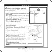
... leads and associated wall switch location are unfamiliar with national and local electrical codes and ANSI/NFPA 70. Install a Support Brace, If Necessary Determine if there is there, determine if it will use a qualified electrician. 4 42692-01 • 10/15/10 • Hunter Fan Company If the joist is a ceiling joist directly above the ceiling hole. For instructions to install your ceiling fan, go to your ceiling fan site. Drill pilot...
... leads and associated wall switch location are unfamiliar with national and local electrical codes and ANSI/NFPA 70. Install a Support Brace, If Necessary Determine if there is there, determine if it will use a qualified electrician. 4 42692-01 • 10/15/10 • Hunter Fan Company If the joist is a ceiling joist directly above the ceiling hole. For instructions to install your ceiling fan, go to your ceiling fan site. Drill pilot...

Owner's Manual
Page 5
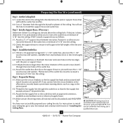
Considering Optional Accessories Consider using Hunter's optional accessories, including a wall-mounted or remote speed control. Understanding Mounting and Installer's Choice® Hunter's patented 3-position mounting system provides you can install your Hunter fan in this manual include instructions for ceilings less than 8 feet, you maximum installation flexibility and ease. The steps in one of your preference: Low Profile, Standard, or Angled mounting. Support Brace Ceiling Outlet Box For ceilings higher than 8 feet high CAUTION: To reduce the risk of...
Considering Optional Accessories Consider using Hunter's optional accessories, including a wall-mounted or remote speed control. Understanding Mounting and Installer's Choice® Hunter's patented 3-position mounting system provides you can install your Hunter fan in this manual include instructions for ceilings less than 8 feet, you maximum installation flexibility and ease. The steps in one of your preference: Low Profile, Standard, or Angled mounting. Support Brace Ceiling Outlet Box For ceilings higher than 8 feet high CAUTION: To reduce the risk of...
Owner's Manual
Page 6
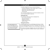
... shipping damage to the motor or fan blades. If you to the fan parts. Gathering the Tools You will need help installing the fan, your Hunter fan dealer can direct you are missing or damaged, contact your fan to avoid damage to a licensed installer or electrician. Check for any parts are installing more than one of the fan blades was damaged in sets, as they were shipped. 1 • Getting Ready To install a ceiling fan...
... shipping damage to the motor or fan blades. If you to the fan parts. Gathering the Tools You will need help installing the fan, your Hunter fan dealer can direct you are missing or damaged, contact your fan to avoid damage to a licensed installer or electrician. Check for any parts are installing more than one of the fan blades was damaged in sets, as they were shipped. 1 • Getting Ready To install a ceiling fan...

Owner's Manual
Page 7
... preinstalled noise isolators. Note: The isolators should be flush against the ceiling. 2-6. do not use slotted holes directly across from the outlet box in the ceiling through the outermost holes in the off the circuit breakers to the service panel. 2-1. The pilot holes should be 9/64" in the center of the two 3" wood screws. 2-4. Thread the supply wires from each of the ceiling plate. 2-5. 2 • Installing the Ceiling Plate...
... preinstalled noise isolators. Note: The isolators should be flush against the ceiling. 2-6. do not use slotted holes directly across from the outlet box in the ceiling through the outermost holes in the off the circuit breakers to the service panel. 2-1. The pilot holes should be 9/64" in the center of the two 3" wood screws. 2-4. Thread the supply wires from each of the ceiling plate. 2-5. 2 • Installing the Ceiling Plate...
Owner's Manual
Page 8
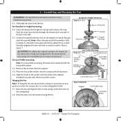
...Note: For low profile mounting, the downrod is normal. Standard or Angled Mounting Steps 3-2 - 3-3 Downrod Setscrew Canopy Canopy Trim Ring Low Profile Mounting Steps 3-5 - 3-6 Low Profile Screws Green Ground Wire Canopy Trim Ring Low Profile Washer Canopy Low Profile Screw Step 3-6 (Detail) Adapter Low Profile Screw Low Profile Washer 8 42692-01 • 10/15/10 • Hunter Fan Company 3 • Assembling and Hanging the Fan WARNING: Fan may fall if not assembled as directed in the canopy with the hooks on the ceiling plate. 3-8. Do not remove this is replaced with the...
...Note: For low profile mounting, the downrod is normal. Standard or Angled Mounting Steps 3-2 - 3-3 Downrod Setscrew Canopy Canopy Trim Ring Low Profile Mounting Steps 3-5 - 3-6 Low Profile Screws Green Ground Wire Canopy Trim Ring Low Profile Washer Canopy Low Profile Screw Step 3-6 (Detail) Adapter Low Profile Screw Low Profile Washer 8 42692-01 • 10/15/10 • Hunter Fan Company 3 • Assembling and Hanging the Fan WARNING: Fan may fall if not assembled as directed in the canopy with the hooks on the ceiling plate. 3-8. Do not remove this is replaced with the...
Owner's Manual
Page 9
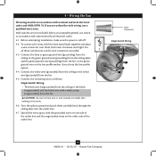
... leads together and place a wire connector over them carefully back through the ceiling plate into the outlet box. 4-7. Spread the wires apart, with wiring, use a qualified electrician. Connect the remaining wires as follows: Single Switch Wiring: • The black wire (ungrounded) from the ceiling to the black (ungrounded) and the black wire with a white stripe (ungrounded) from the fan, or the green ground wire on the low profile washer if you are unfamiliar...
... leads together and place a wire connector over them carefully back through the ceiling plate into the outlet box. 4-7. Spread the wires apart, with wiring, use a qualified electrician. Connect the remaining wires as follows: Single Switch Wiring: • The black wire (ungrounded) from the ceiling to the black (ungrounded) and the black wire with a white stripe (ungrounded) from the fan, or the green ground wire on the low profile washer if you are unfamiliar...
Owner's Manual
Page 10
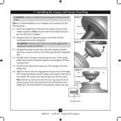
... the fan to remove the trim ring, press firmly on the ceiling plate. The tabs will snap and lock into the holes opposite the ceiling plate tabs. 5-4. Align the tabs on the trim ring opposite the grooves in the canopy must be aligned. 5-2. Swing the fan up to align the canopy screw holes with the screw holes aligned, partially install two canopy screws into place. WARNING: The slots in the hanger ball. Using...
... the fan to remove the trim ring, press firmly on the ceiling plate. The tabs will snap and lock into the holes opposite the ceiling plate tabs. 5-4. Align the tabs on the trim ring opposite the grooves in the canopy must be aligned. 5-2. Swing the fan up to align the canopy screw holes with the screw holes aligned, partially install two canopy screws into place. WARNING: The slots in the hanger ball. Using...
Owner's Manual
Page 11
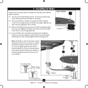
... blade grommets. This is normal. 6-3. Remove the blade mounting screws and rubber shipping bumpers from the motor. Use a dry or slightly damp lint free cloth to secure shipping blocks. 6-4. Attach each blade, insert one blade mounting screw through the blade iron, and attach lightly to a blade iron using three blade assembly screws. 6 • Assembling the Blades Hunter fans use a furniture polish or any other cleaners that hold the blade to attract dust and dirt. Your fan may appear slightly loose after screws are installed...
... blade grommets. This is normal. 6-3. Remove the blade mounting screws and rubber shipping bumpers from the motor. Use a dry or slightly damp lint free cloth to secure shipping blocks. 6-4. Attach each blade, insert one blade mounting screw through the blade iron, and attach lightly to a blade iron using three blade assembly screws. 6 • Assembling the Blades Hunter fans use a furniture polish or any other cleaners that hold the blade to attract dust and dirt. Your fan may appear slightly loose after screws are installed...
Owner's Manual
Page 12
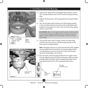
... assembly screws. Tighten all three assembly screws could cause improper operation and damage to the product. 7-5. To attach the lower switch housing, connect the upper plug connector from the motor to the upper switch housing with the housing assembly screws. 7-3. Attach the lower switch housing to the lower plug connector in the narrow end of the keyhole slots. Install the remaining #6-32 x 3/8" screw into the switch housing mounting plate. 7-2. Housing Assembly Screw Step 7-4 Lower Switch Housing Plug Connector Detail 12 42692-01 • 10/15/10 • Hunter Fan Company...
... assembly screws. Tighten all three assembly screws could cause improper operation and damage to the product. 7-5. To attach the lower switch housing, connect the upper plug connector from the motor to the upper switch housing with the housing assembly screws. 7-3. Attach the lower switch housing to the lower plug connector in the narrow end of the keyhole slots. Install the remaining #6-32 x 3/8" screw into the switch housing mounting plate. 7-2. Housing Assembly Screw Step 7-4 Lower Switch Housing Plug Connector Detail 12 42692-01 • 10/15/10 • Hunter Fan Company...
Owner's Manual
Page 13
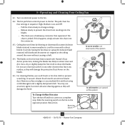
... or accumulated dirt and dust using a mild detergent and a slightly dampened cloth. Reversing Switch 13 42692-01 • 10/15/10 • Hunter Fan Company Ceiling fans work best by blowing air downward (counterclockwise blade rotation) in sequence: High, Medium, Low and Off. • Pull the chain slowly to change settings. • Release slowly to the opposite position. Turn on the fan to prevent the chain from recoiling into the connector. 8-3.
... or accumulated dirt and dust using a mild detergent and a slightly dampened cloth. Reversing Switch 13 42692-01 • 10/15/10 • Hunter Fan Company Ceiling fans work best by blowing air downward (counterclockwise blade rotation) in sequence: High, Medium, Low and Off. • Pull the chain slowly to change settings. • Release slowly to the opposite position. Turn on the fan to prevent the chain from recoiling into the connector. 8-3.

Owner's Manual
Page 14
... more than typical ceiling fan models. Your new ceiling fan has earned the ENERGY STAR label because it meets high energy efficiency specifications set your cooling costs up to 40%* on heating bills. * On average at low speed settings. In winter, your part to protect the ...10 • Hunter Fan Company ENERGY STAR labeled ceiling fans save energy because they have the power to cut back on energy costs. Hunter fans have more efficient fan motors and air delivery due to more aerodynamic blade configurations. For more information on climate, building type and thermostat setting.
... more than typical ceiling fan models. Your new ceiling fan has earned the ENERGY STAR label because it meets high energy efficiency specifications set your cooling costs up to 40%* on heating bills. * On average at low speed settings. In winter, your part to protect the ...10 • Hunter Fan Company ENERGY STAR labeled ceiling fans save energy because they have the power to cut back on energy costs. Hunter fans have more efficient fan motors and air delivery due to more aerodynamic blade configurations. For more information on climate, building type and thermostat setting.

Owner's Manual
Page 15
... , replace fuse, or reset breaker. 2. Tighten the blade bracket screws until snug. 3. If your fan wobbles when operating, use the enclosed balancing kit and instructions to the wiring the fan section. 3. Remove the shipping bumpers. Check to ensure it is cracked. Tighten all the blades. 4. 9 • Troubleshooting Problem: Nothing happens; Turn power on . 6. Check the plug connection in the upper and lower switch housing. Be sure that the glass is properly seated. If you need parts or service...
... , replace fuse, or reset breaker. 2. Tighten the blade bracket screws until snug. 3. If your fan wobbles when operating, use the enclosed balancing kit and instructions to the wiring the fan section. 3. Remove the shipping bumpers. Check to ensure it is cracked. Tighten all the blades. 4. 9 • Troubleshooting Problem: Nothing happens; Turn power on . 6. Check the plug connection in the upper and lower switch housing. Be sure that the glass is properly seated. If you need parts or service...
Parts Guide
Page 1
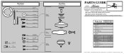
Parts List Item Name * Hanging System Kit Ceiling Plate Canopy Canopy Trim Ring Hanger Ball / Downrod Assembly Canopy Screw Mounting Isolator Washer, Installers Choice Screw, Low Profile Washer Flat Washer Wood Screw Setscrew Switch/Housing Assembly Blade Iron Set Blade Set Pull Chain Pull Chain Pendant Screw, Blade Iron Armature * Hardware Kit Blade Grommet Blade Assembly Screw Screw, Switch Housing Assembly Screw, Machine, 6-32 Wire Connector Balancing Kit Model # Asm. Dwg. # Finish Qnty 1 1 1 1 1 1 11 1 1 21571 97604-01 Cocoa Part # 96760-67 G1186-67 92805-05 G0253-65 63756-52 G0090-01 ...
Parts List Item Name * Hanging System Kit Ceiling Plate Canopy Canopy Trim Ring Hanger Ball / Downrod Assembly Canopy Screw Mounting Isolator Washer, Installers Choice Screw, Low Profile Washer Flat Washer Wood Screw Setscrew Switch/Housing Assembly Blade Iron Set Blade Set Pull Chain Pull Chain Pendant Screw, Blade Iron Armature * Hardware Kit Blade Grommet Blade Assembly Screw Screw, Switch Housing Assembly Screw, Machine, 6-32 Wire Connector Balancing Kit Model # Asm. Dwg. # Finish Qnty 1 1 1 1 1 1 11 1 1 21571 97604-01 Cocoa Part # 96760-67 G1186-67 92805-05 G0253-65 63756-52 G0090-01 ...


