Installation Instructions
Page 1
... cause a hazardous condition. 2. Registered Trademark Copyright © 2004 Honeywell International Inc. • • All Rights Reserved 69-1740 The T8400C and T8401C models include a thermostat, wallplate (for operation. Failure to Wall IMPORTANT Level only for ...Thermostat is fixed at the factory. Do not install the thermostat where it carefully. Place the wallplate at 1, 3, 4, 5, 6, 9, or 12 cph. T8400C, T8401C Electronic Thermostats INSTALLATION INSTRUCTIONS The T8400C and T8401C Thermostats provide singlestage, non-programmable temperature control for 24V heating...
... cause a hazardous condition. 2. Registered Trademark Copyright © 2004 Honeywell International Inc. • • All Rights Reserved 69-1740 The T8400C and T8401C models include a thermostat, wallplate (for operation. Failure to Wall IMPORTANT Level only for ...Thermostat is fixed at the factory. Do not install the thermostat where it carefully. Place the wallplate at 1, 3, 4, 5, 6, 9, or 12 cph. T8400C, T8401C Electronic Thermostats INSTALLATION INSTRUCTIONS The T8400C and T8401C Thermostats provide singlestage, non-programmable temperature control for 24V heating...
Installation Instructions
Page 2
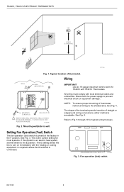
... 1 WHEN USING WALL ANCHORS, DRILL 3/16 INCH HOLES FOR DRYWALL, 7/32 INCH HOLES FOR PLASTER OR WOOD. either method is an electric heat system, set the switch to the E position. The E setting allows the fan to Fig. 6 through 10 for most systems. If this... to turn on immediately with local electrical codes and ordinances. E F FAN OPERATION (FUEL) SWITCH M12580 Fig. 3. T8400C, T8401C ELECTRONIC THERMOSTATS YES NO NO 5 FEET [1.5 METERS] NO M11338 Fig. 1. NOTE: To ensure proper mounting of thermostat, restrict all wiring to prevent electrical shock or equipment damage.
... 1 WHEN USING WALL ANCHORS, DRILL 3/16 INCH HOLES FOR DRYWALL, 7/32 INCH HOLES FOR PLASTER OR WOOD. either method is an electric heat system, set the switch to the E position. The E setting allows the fan to Fig. 6 through 10 for most systems. If this... to turn on immediately with local electrical codes and ordinances. E F FAN OPERATION (FUEL) SWITCH M12580 Fig. 3. T8400C, T8401C ELECTRONIC THERMOSTATS YES NO NO 5 FEET [1.5 METERS] NO M11338 Fig. 1. NOTE: To ensure proper mounting of thermostat, restrict all wiring to prevent electrical shock or equipment damage.
Installation Instructions
Page 3
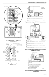
... STRIP 7/16 IN. (11 MM) Rc R W Y B O M13274 Fig. 5. Typical hookup of T8400C in heat-cool system with two transformers. PROVIDE DISCONNECT MEANS AND OVERLOAD PROTECTION AS REQUIRED. 2 CAN BE USED FOR CHANGEOVER VALVE ON SINGLE-STAGE...POSITION. Typical hookup of T8400C in heat-cool system with single transformer. G Rc R 24 W B Y O 1 L1 (HOT) L2 FAN RELAY 3 COOL DAMPER 3 HEAT DAMPER COMPRESSOR CONTACTOR HEAT RELAY 1 L1 (HOT) L2 COOLING TRANSFORMER HEATING TRANSFORMER 1 POWER SUPPLY. T8400C, T8401C ELECTRONIC THERMOSTATS KEEP WIRING IN SHADED AREA G Rc...
... STRIP 7/16 IN. (11 MM) Rc R W Y B O M13274 Fig. 5. Typical hookup of T8400C in heat-cool system with two transformers. PROVIDE DISCONNECT MEANS AND OVERLOAD PROTECTION AS REQUIRED. 2 CAN BE USED FOR CHANGEOVER VALVE ON SINGLE-STAGE...POSITION. Typical hookup of T8400C in heat-cool system with single transformer. G Rc R 24 W B Y O 1 L1 (HOT) L2 FAN RELAY 3 COOL DAMPER 3 HEAT DAMPER COMPRESSOR CONTACTOR HEAT RELAY 1 L1 (HOT) L2 COOLING TRANSFORMER HEATING TRANSFORMER 1 POWER SUPPLY. T8400C, T8401C ELECTRONIC THERMOSTATS KEEP WIRING IN SHADED AREA G Rc...
Installation Instructions
Page 4
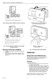
... Room AuFtoANOn CoSoYl SOTffEMHeat A ENGAGE TABS AT TOP OF THERMOSTAT WITH SLOTS ON MOUNTING PLATE. Mounting Thermostat to select the desired fan setting. 69-1740 4 Mounting thermostat wallplate. Auto: Normal setting for improved air circulation and air quality. T8400C, T8401C ELECTRONIC THERMOSTATS G C R W B Y O 1 L1 (HOT) 24V L2 TRANSFORMER HEAT RELAY COOL RELAY FAN RELAY 1 POWER SUPPLY. M20881...
... Room AuFtoANOn CoSoYl SOTffEMHeat A ENGAGE TABS AT TOP OF THERMOSTAT WITH SLOTS ON MOUNTING PLATE. Mounting Thermostat to select the desired fan setting. 69-1740 4 Mounting thermostat wallplate. Auto: Normal setting for improved air circulation and air quality. T8400C, T8401C ELECTRONIC THERMOSTATS G C R W B Y O 1 L1 (HOT) 24V L2 TRANSFORMER HEAT RELAY COOL RELAY FAN RELAY 1 POWER SUPPLY. M20881...
Installation Instructions
Page 5
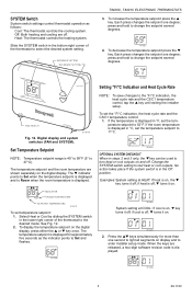
...°C. M14680 Setting °F/°C Indication and Heat Cycle Rate NOTE: To save changes to test heat or cool outputs. If the temperature is displayed. INCREASE SETTING DECREASE SETTING T8400C, T8401C ELECTRONIC THERMOSTATS 3. M14681 4. M14683 OPTIONAL SYSTEM CHECKOUT When in... the Off position. Off: Both heating and cooling are released, a two-digit software revision code is displayed in...
...°C. M14680 Setting °F/°C Indication and Heat Cycle Rate NOTE: To save changes to test heat or cool outputs. If the temperature is displayed. INCREASE SETTING DECREASE SETTING T8400C, T8401C ELECTRONIC THERMOSTATS 3. M14681 4. M14683 OPTIONAL SYSTEM CHECKOUT When in... the Off position. Off: Both heating and cooling are released, a two-digit software revision code is displayed in...
Installation Instructions
Page 6
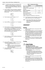
... (varies by model) is shown, but information displayed varies by model. After approximately ten seconds, the heating equipment should stop. When using an electric heat thermostat, the fan starts immediately. 3. Slide the SYSTEM switch to Cool and the FAN switch to scroll between...Standard heating/cooling temperature control. Press the ▼ key to equipment manufacturer's instructions. 10. After approximately five minutes, the cooling equipment should start . bRefer to lower the temperature setting below the room temperature. T8400C, T8401C ELECTRONIC THERMOSTATS NOTE:...
... (varies by model) is shown, but information displayed varies by model. After approximately ten seconds, the heating equipment should stop. When using an electric heat thermostat, the fan starts immediately. 3. Slide the SYSTEM switch to Cool and the FAN switch to scroll between...Standard heating/cooling temperature control. Press the ▼ key to equipment manufacturer's instructions. 10. After approximately five minutes, the cooling equipment should start . bRefer to lower the temperature setting below the room temperature. T8400C, T8401C ELECTRONIC THERMOSTATS NOTE:...
Installation Instructions
Page 7
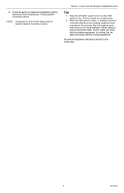
...above the room temperature. 3. Press the ▲ key to Auto. T8400C, T8401C ELECTRONIC THERMOSTATS Fan 1. In heating, the fan is controlled directly by the heating equipment and may start a few minutes after the heating equipment turns on (on most systems). NOTE: To bypass the five-minute delay, ...On. In cooling, the fan starts and stops with the heating equipment. Cooling system should run continuously. 2. Slide the SYSTEM switch to Off and the FAN switch to the thermostat. 7 69-1740 When using an electric heat thermostat, the fan starts and stops with the cooling equipment.
...above the room temperature. 3. Press the ▲ key to Auto. T8400C, T8401C ELECTRONIC THERMOSTATS Fan 1. In heating, the fan is controlled directly by the heating equipment and may start a few minutes after the heating equipment turns on (on most systems). NOTE: To bypass the five-minute delay, ...On. In cooling, the fan starts and stops with the heating equipment. Cooling system should run continuously. 2. Slide the SYSTEM switch to Off and the FAN switch to the thermostat. 7 69-1740 When using an electric heat thermostat, the fan starts and stops with the cooling equipment.


