Honeywell Heat/1Cool - T841A1563 Premier 2 Stage Thermostat Support and Manuals
Get Help and Manuals for this Honeywell item
View All Support Options Below
Free Honeywell Heat/1Cool manuals!
Problems with Honeywell Heat/1Cool?
Ask a Question
Free Honeywell Heat/1Cool manuals!
Problems with Honeywell Heat/1Cool?
Ask a Question
Most Recent Honeywell Heat/1Cool Questions

My Ac Unit Wont Turn On Tried To Reprogram But Having Trouble, How Do I Clear?
what does -AC mean on the thermostat? the batteries were replaced but it wont let me change the days...
what does -AC mean on the thermostat? the batteries were replaced but it wont let me change the days...
(Posted by romocrissy 9 years ago)
Popular Honeywell Heat/1Cool Manual Pages
User Guide - Page 2
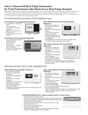
... any décor.
• Two heat/one cool; automatic or
manual changeover. • Two-piece, front-wired construc- Honeywell heat pump thermostats are ideal for Peak Performance that Meets Every Heat Pump Demand
Rapid advances in heat pump technology, resulting in high efficiency units and lower operating costs, have made the heat pump a popular choice with excellent temperature control...
User Guide - Page 3
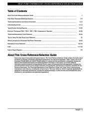
.../Selection Guide ...
1
Heat Pump Thermostat Model Specifications ...
2-4
Thermostat Descriptions and General Information ...
5-12
Understanding Circuits ...13-14
Typical System Hookup Diagrams ...15-25
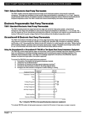
Electronic Thermostat (T8011, T8411, T8511, T8611) Sequences of selecting a Honeywell replacement thermostat for any Honeywell heat pump thermostat in new installations and replacement...
User Guide - Page 7
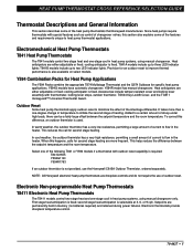
... T841 or Y594 models if a thermostat with special features such as control of changeover valves, this difference, an outdoor thermistor is used. cooling anticipator is fixed. Provision for specific heat pump applications. In cool weather, the outdoor thermistor has a very high resistance, permitting a small amount of current to flow in heat pump systems, using manual changeover. This...
User Guide - Page 8
... a On selected T8611M models, the high speed compressor is wired to the high-speed compressor terminal.a 4.
The T8511 models also include a backlit display and outdoor sensing capability. All programs and setpoints are permanently held in heat pump systems, using manual or automatic changeover.
However, there is a three-stage heat/two-stage cool thermostat used to the...
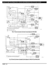
User Guide - Page 15

... CUTOFF
M5848
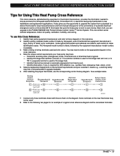
Fig. 14. HEAT PUMP THERMOSTAT CROSS REFERENCE/SELECTION GUIDE
Understanding Circuits
To understand wiring diagrams, it is important to know what all the symbols mean and how to trace the path of an AUTO position in the system switching (EX: Q674F with OFF-COOL AUTO-HEAT-EM. Cool changeover valve-operates on heating. The system monitor relay may be...
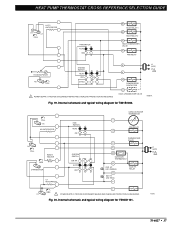
User Guide - Page 17

... (RED)
B
RTD 1
RD EM. HT. HT. Internal schematic and typical wiring diagram for T841A1308.
70-6627 • 15 LED (GREEN)
E
L EM.
RELAY
SYSTEM MONITOR
X LACO
Y
HEAT CHANGEOVER VALVE
COMPRESSOR CONTACTOR O
COOL CHANGEOVER VALVE
CHP
M6060A
Fig. 16. HEAT PUMP THERMOSTAT CROSS REFERENCE/SELECTION GUIDE
Typical System Hookup Diagrams
L1 L2 (HOT)
RTD 1
1 ODT 1
H1 C1
FALL...
User Guide - Page 18
...
11
FAN SWITCH AUTO
ON
SYSTEM SWITCH
EM. Internal schematic and typical wiring diagram for T841A1555. COMPRESSOR MONITOR
R OUTDOOR THERMOSTAT
X2
T
OUTDOOR
O
THERMISTOR
COOL CHANGEOVER RELAY
COMPRESSOR CONTACTOR
Y
2 FIELD REMOVABLE JUMPER.
3 AUTO FAN IN EMERGENCY HEAT. HEAT OFF COOL
1 POWER SUPPLY. W3
O
EM. HEAT RELAY
B HEAT CHANGEOVER RELAY COMPRESSOR CONTACTOR
Y
Fig...
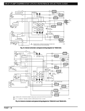
User Guide - Page 19
... typical wiring diagram for T841B1000. FALL H1
H1 ANTICIPATOR
H2 FALL
RESET HEATER
RISE
CHANGEOVER
C1 ANTICIPATOR
FAN SWITCH AUTO
ON
SYSTEM SWITCH EM .HT.
HEAT PUMP THERMOSTAT CROSS REFERENCE/SELECTION GUIDE
H1/C1 ANTICIPATOR
H1
C1
FALL
FAN SWITCH AUTO
ON
W1 HEAT RELAY 1
W2 HEAT RELAY 2
B HEAT CHANGEOVER VALVE
G FAN RELAY
H2 ANTICIPATOR
H2 FALL
SYSTEM SWITCH
HEAT OFF
COOL...
User Guide - Page 20
...)
L2 1
Y
1 POWER SUPPLY. Internal schematic and typical wiring diagram for Y594G1419 and Y594G1476.
70-6627 • 18 HEAT
AUTO COOL
W2
E AUX. HEAT PUMP THERMOSTAT CROSS REFERENCE/SELECTION GUIDE
FALL
1 H1 ANTICIPATOR
2
H1 4
6 H2 ANTICIPATOR
H2 FALL
RISE 8
C1
9
C1 ANTICIPATOR 10
11 RISE CO
12
FAN SWITCH AUTO ON
SYSTEM SWITCH
OFF EM.
RELAY
L
EM. LED (RED...
User Guide - Page 35
... the appropriate diagram in new installations and replacement applications. Identify what action, if any, is used for first stage heat and cool, or to cool. - Existing Control Terminal Designation
Electromechanical Chronotherm III
Thermostat
Thermostat
Electronic Replacement or Upgrade
Perfect Climate
Chronotherm IV Comfort Center Thermostat Control System
C Hook wire X
or to
C
or to...
User Guide - Page 41
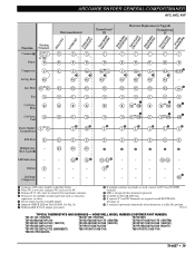
...Installer Setup. · When W2 is not used, configure W2 cycle rate to NC. » Terminal X (C, X1) must be connected to W2 (Aux W8900B) terminal.
¾ LED is energized when terminal is powered. µ Available on T8611G1004.
HONEYWELL MODEL NUMBER (CUSTOMER PART...; 39 Heat
or W2 W1
W2
Fan
G
G
C/O Valve
B
B
Heat
C/O Valve
O
O
Cool
System Monitor/
or L X
System Defrost
X...
User Guide - Page 42
...40
TYPICAL THERMOSTATS AND SUBBASES - X1 X2
-
·
-
-
-
-
- X2 º
X2 º
2nd Stage
-
-
-
-
Heat
-
- Compressor
³ Configure O/B (select models) in Em. E
E
E
E
E
E
»
»
»
»
»
»
X1 X2
-
-
- Heat
W2
W2
Fan
G
G
C/O Valve
or B W1
B
Heat
C/O Valve
O
O
Cool
System Monitor/
L
System Defrost
X
R
Y ²...
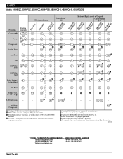
User Guide - Page 43

...X1 and X2 terminals. Ƹ L terminal is powered continuously when thermostat is for multiple second stage heating loads such as contactors,
sequencers, or relays. ´ Model 545 typical. B.D.P. (BRYANT-DAY/NIGHT-PAYNE)
Electromechanical
Chronotherm® III
Electronic Replacement or Upgrade
Chronotherm IV
T841A1712 Y594R1425 Y5Y9549G41G4174619 T8T681611G11R0100400 T8T481411R11R0120802...
User Guide - Page 44

... Heat Loads ¿
LED Indication
-
- X1 X2
-
Ht. M13147
TYPICAL THERMOSTATS AND SUBBASES - HONEYWELL MODEL NUMBER (CUSTOMER PART NUMBER... factory-installed jumper.
¶ Optional CHECK LED on T8611G1004. X2 º
X2 º
¶ X1 X2
-
-
- Compressor
-
-
·
-
-
-
-
-
Fan
G
G
C/O Valve
B
B
Heat
C/O Valve
O
O
Cool
System Monitor/ System Defrost...
User Guide - Page 89

... is powered. Ƹ L terminal is powered continuously when thermostat is in Installer Setup. · When W2 is not used, configure W2 cycle rate to NC. » Terminal is for multiple auxiliary heat loads such as contactors, sequencers,
or relays. ¿ Disconnect external timimg device from circuit before wiring replacement
thermostat. ´ Optional LED indication activated with completed...
Honeywell Heat/1Cool Reviews
We have not received any reviews for Honeywell yet.