User Guide
Page 2
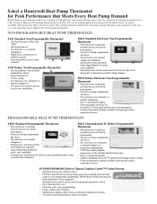
... -one cool; Select a Honeywell Heat Pump Thermostat for quick, easy readability. • Conveniently sized thermostat with two-piece installation make it easy to install and troubleshoot. Because your heat pump applications and provide the highest level of heat pump thermostats. NON-PROGRAMMABLE HEAT PUMP THERMOSTATS T841 Standard Non-Programmable Thermostat • Good performance without any décor. • Two heat/one cool; automatic...
... -one cool; Select a Honeywell Heat Pump Thermostat for quick, easy readability. • Conveniently sized thermostat with two-piece installation make it easy to install and troubleshoot. Because your heat pump applications and provide the highest level of heat pump thermostats. NON-PROGRAMMABLE HEAT PUMP THERMOSTATS T841 Standard Non-Programmable Thermostat • Good performance without any décor. • Two heat/one cool; automatic...
User Guide
Page 8
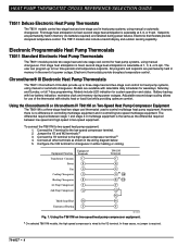
... Common C Power R Fan G Cooling Changeover O Heating Changeover B 1st Stage Compressor Y 2nd Stage Compressor Y2 Third Stage Heat W3 Emergency Heating E T8611M Terminals C R G or O O/B or B O/B Y a Y2 W2 W3 E M13229 Fig. 1. second stage heat anticipation is wired to control multistage heat pump equipment. The T8511 models also include a backlit display and outdoor sensing capability. second stage heat anticipation is a three-stage heat/two-stage cool thermostat used to the Y2...
... Common C Power R Fan G Cooling Changeover O Heating Changeover B 1st Stage Compressor Y 2nd Stage Compressor Y2 Third Stage Heat W3 Emergency Heating E T8611M Terminals C R G or O O/B or B O/B Y a Y2 W2 W3 E M13229 Fig. 1. second stage heat anticipation is wired to control multistage heat pump equipment. The T8511 models also include a backlit display and outdoor sensing capability. second stage heat anticipation is a three-stage heat/two-stage cool thermostat used to the Y2...
User Guide
Page 9
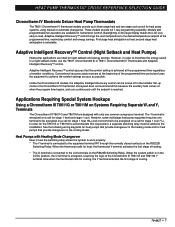
... O terminal is in the cooling model. Honeywell does not recommend this requirement, a separate switching relay must be energized on a call for night setback and energy savings. When the system switch is connected to be added to three-stage heat and two-stage cool control for homeowner comfort. Now when the thermostat calls for heat pumps that provide changeover...
... O terminal is in the cooling model. Honeywell does not recommend this requirement, a separate switching relay must be energized on a call for night setback and energy savings. When the system switch is connected to be added to three-stage heat and two-stage cool control for homeowner comfort. Now when the thermostat calls for heat pumps that provide changeover...
User Guide
Page 11
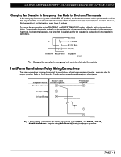
... Control Equipment Function Terminal Designation Transformer Common C 1st Stage Cooling Y1 1st Stage Heating W1 New Terminal Designation C Y O M13235 Fig. 5. R (Power) E C (Common) E (EM. Heat) G G (Fan) Thermostat R8222B Relay Equipment M13232 Fig. 4 Changing fan operation in emergency heat mode for first stage heat. Require relay (R8222B1067 typically) for Electronic Thermostats In the emergency heat mode (system switch in EM. Refer to specific...
... Control Equipment Function Terminal Designation Transformer Common C 1st Stage Cooling Y1 1st Stage Heating W1 New Terminal Designation C Y O M13235 Fig. 5. R (Power) E C (Common) E (EM. Heat) G G (Fan) Thermostat R8222B Relay Equipment M13232 Fig. 4 Changing fan operation in emergency heat mode for first stage heat. Require relay (R8222B1067 typically) for Electronic Thermostats In the emergency heat mode (system switch in EM. Refer to specific...
User Guide
Page 14
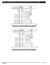
... R Fan G 1st Stage Cooling Y1 1st Stage Heating W1 Changeover Valve O PC8900 Terminals C R G O/B Y1/W1 2nd Stage Heating W2 Aux. Emergency Heat E E 2nd Stage Cooling Y2 Y2 M13233 Fig. 12. Relay wiring connections for PC8900 in heat pump applications requiring separate Y1 and W1 terminals with a cooling changeover. 70-6627 • 12 Emergency Heat E E 2nd Stage Cooling Y2 Y2 M13234 Fig. 13. HEAT PUMP THERMOSTAT CROSS REFERENCE...
... R Fan G 1st Stage Cooling Y1 1st Stage Heating W1 Changeover Valve O PC8900 Terminals C R G O/B Y1/W1 2nd Stage Heating W2 Aux. Emergency Heat E E 2nd Stage Cooling Y2 Y2 M13233 Fig. 12. Relay wiring connections for PC8900 in heat pump applications requiring separate Y1 and W1 terminals with a cooling changeover. 70-6627 • 12 Emergency Heat E E 2nd Stage Cooling Y2 Y2 M13234 Fig. 13. HEAT PUMP THERMOSTAT CROSS REFERENCE...

User Guide
Page 15
... Fig. 14. HEAT PUMP THERMOSTAT CROSS REFERENCE/SELECTION GUIDE Understanding Circuits To understand wiring diagrams, it is important to know what all the symbols mean and how to HEAT (manual changeover) or by function: H1-Stage 1 Heating. HT.-HEAT-OFFCOOL switching). Heat changeover valve-operates on cooling. System monitor relay-optional equipment on some heat pumps. H2-Stage 2 Heating. C3-Stage 3 Cooling. All T874...
... Fig. 14. HEAT PUMP THERMOSTAT CROSS REFERENCE/SELECTION GUIDE Understanding Circuits To understand wiring diagrams, it is important to know what all the symbols mean and how to HEAT (manual changeover) or by function: H1-Stage 1 Heating. HT.-HEAT-OFFCOOL switching). Heat changeover valve-operates on cooling. System monitor relay-optional equipment on some heat pumps. H2-Stage 2 Heating. C3-Stage 3 Cooling. All T874...

User Guide
Page 17
HEAT OFF COOL SYSTEM SWITCH 1 POWER SUPPLY. W2 AUX. HT. PROVIDE DISCONNECT MEANS AND OVERLOAD PROTECTION AS REQUIRED. 2 NO AUTO FAN IN EMERGENCY HEAT. HT. Internal schematic and typical wiring diagram for T841A1308. 70-6627 • 15 HEAT PUMP THERMOSTAT CROSS REFERENCE/SELECTION GUIDE Typical System Hookup Diagrams L1 L2 (HOT) RTD 1 1 ODT 1 H1 C1 FALL H1...
HEAT OFF COOL SYSTEM SWITCH 1 POWER SUPPLY. W2 AUX. HT. PROVIDE DISCONNECT MEANS AND OVERLOAD PROTECTION AS REQUIRED. 2 NO AUTO FAN IN EMERGENCY HEAT. HT. Internal schematic and typical wiring diagram for T841A1308. 70-6627 • 15 HEAT PUMP THERMOSTAT CROSS REFERENCE/SELECTION GUIDE Typical System Hookup Diagrams L1 L2 (HOT) RTD 1 1 ODT 1 H1 C1 FALL H1...
User Guide
Page 18
... 3 EM. COMPRESSOR MONITOR R OUTDOOR THERMOSTAT X2 T OUTDOOR O THERMISTOR COOL CHANGEOVER RELAY COMPRESSOR CONTACTOR Y 2 FIELD REMOVABLE JUMPER. 3 AUTO FAN IN EMERGENCY HEAT. HT. W3 O EM. HEAT LED (GRN) W2 FAN RELAY EM. HEAT OFF 1 RESET 4 COOL 1 POWER SUPPLY. PROVIDE DISCONNECT MEANS AND OVERLOAD PROTECTION AS REQUIRED. HEAT RELAY B HEAT CHANGEOVER RELAY COMPRESSOR CONTACTOR Y Fig. 18. HEAT LED (RED) FAN RELAY...
... 3 EM. COMPRESSOR MONITOR R OUTDOOR THERMOSTAT X2 T OUTDOOR O THERMISTOR COOL CHANGEOVER RELAY COMPRESSOR CONTACTOR Y 2 FIELD REMOVABLE JUMPER. 3 AUTO FAN IN EMERGENCY HEAT. HT. W3 O EM. HEAT LED (GRN) W2 FAN RELAY EM. HEAT OFF 1 RESET 4 COOL 1 POWER SUPPLY. PROVIDE DISCONNECT MEANS AND OVERLOAD PROTECTION AS REQUIRED. HEAT RELAY B HEAT CHANGEOVER RELAY COMPRESSOR CONTACTOR Y Fig. 18. HEAT LED (RED) FAN RELAY...
User Guide
Page 19
...C1 1 POWER SUPPLY. Internal schematic and typical wiring diagram for T841B1000. FALL H1 H1 ANTICIPATOR H2 FALL RESET HEATER RISE CHANGEOVER C1 ANTICIPATOR FAN SWITCH AUTO ON SYSTEM SWITCH EM .HT. HEAT PUMP THERMOSTAT CROSS REFERENCE/SELECTION GUIDE H1/C1 ANTICIPATOR H1 C1... FALL FAN SWITCH AUTO ON W1 HEAT RELAY 1 W2 HEAT RELAY 2 B HEAT CHANGEOVER VALVE G FAN RELAY H2 ANTICIPATOR H2 FALL SYSTEM SWITCH HEAT OFF COOL 1 POWER SUPPLY. R L1 (HOT) L2 1 X Y1 COMPRESSOR CONTACTOR O COOL CHANGEOVER...
...C1 1 POWER SUPPLY. Internal schematic and typical wiring diagram for T841B1000. FALL H1 H1 ANTICIPATOR H2 FALL RESET HEATER RISE CHANGEOVER C1 ANTICIPATOR FAN SWITCH AUTO ON SYSTEM SWITCH EM .HT. HEAT PUMP THERMOSTAT CROSS REFERENCE/SELECTION GUIDE H1/C1 ANTICIPATOR H1 C1... FALL FAN SWITCH AUTO ON W1 HEAT RELAY 1 W2 HEAT RELAY 2 B HEAT CHANGEOVER VALVE G FAN RELAY H2 ANTICIPATOR H2 FALL SYSTEM SWITCH HEAT OFF COOL 1 POWER SUPPLY. R L1 (HOT) L2 1 X Y1 COMPRESSOR CONTACTOR O COOL CHANGEOVER...
User Guide
Page 20
...EM. Y1 JUMPER IS Y TERMINAL; HT. HT. HT. HEAT LED (GREEN) AUX. Internal schematic and typical wiring diagram for Y594G1419 and Y594G1476. 70-6627 • 18 HT. M8703 Fig. 22. HT. HT. HEAT PUMP THERMOSTAT CROSS REFERENCE/SELECTION GUIDE FALL 1 H1 ANTICIPATOR 2 H1 4 ... EM. PROVIDE DISCONNECT MEANS AND OVERLOAD PROTECTION AS REQUIRED. LED (RED) X COOL CHANGEOVER VALVE O B W1 RELAY W1 HEAT CHANGEOVER VALVE 2 COMPRESSOR CONTACTOR Y1 1 POWER SUPPLY. RELAY L EM. HEAT AUTO COOL W2 E AUX. COMPRESSOR CONTACTOR M8702 Fig. 21. PROVIDE DISCONNECT MEANS AND OVERLOAD...
...EM. Y1 JUMPER IS Y TERMINAL; HT. HT. HT. HEAT LED (GREEN) AUX. Internal schematic and typical wiring diagram for Y594G1419 and Y594G1476. 70-6627 • 18 HT. M8703 Fig. 22. HT. HT. HEAT PUMP THERMOSTAT CROSS REFERENCE/SELECTION GUIDE FALL 1 H1 ANTICIPATOR 2 H1 4 ... EM. PROVIDE DISCONNECT MEANS AND OVERLOAD PROTECTION AS REQUIRED. LED (RED) X COOL CHANGEOVER VALVE O B W1 RELAY W1 HEAT CHANGEOVER VALVE 2 COMPRESSOR CONTACTOR Y1 1 POWER SUPPLY. RELAY L EM. HEAT AUTO COOL W2 E AUX. COMPRESSOR CONTACTOR M8702 Fig. 21. PROVIDE DISCONNECT MEANS AND OVERLOAD...
User Guide
Page 21
... for Y594R1797. Internal schematic and typical wiring diagram for Y594R1763. 2 H1 AND C1 ANTICIPATOR 3 H1 FALL FALL C1 4 H2 ANTICIPATOR H2 6 FAN SWITCH AUTO ON SYSTEM SWITCH EM. AUX. HEAT RELAY W2 FAN RELAY G COOL CHANGEOVER VALVE O COOL E COMPRESSOR EM. HEAT LED (GREEN) EM. HT. HEAT LED (GRN) AUX. HEAT PUMP THERMOSTAT CROSS REFERENCE/SELECTION GUIDE 1 2 H1 C1...
... for Y594R1797. Internal schematic and typical wiring diagram for Y594R1763. 2 H1 AND C1 ANTICIPATOR 3 H1 FALL FALL C1 4 H2 ANTICIPATOR H2 6 FAN SWITCH AUTO ON SYSTEM SWITCH EM. AUX. HEAT RELAY W2 FAN RELAY G COOL CHANGEOVER VALVE O COOL E COMPRESSOR EM. HEAT LED (GREEN) EM. HT. HEAT LED (GRN) AUX. HEAT PUMP THERMOSTAT CROSS REFERENCE/SELECTION GUIDE 1 2 H1 C1...
User Guide
Page 22
...HEAT PUMP THERMOSTAT CROSS REFERENCE/SELECTION GUIDE W3 W3 RELAY H1 ANTICIPATOR 1 C ANTICIPATOR 2 FAN SWITCH AUTO ON H1 3 C FALL 4 5 H2 ANTICIPATOR H2 6 FALL SYSTEM SWITCH EM. HT. HT. RELAY X 3 X2 HEAT CHANGEOVER VALVE B W1 RELAY W1 2 COMPRESSOR CONTACTOR Y L1 (HOT) L2 1 M8713 Fig. 25. Internal schematic and typical wiring... diagram for Y594R1425. 70-6627 • 20 O COOL CHANGEOVER VALVE L COMPRESSOR MONITOR ...
...HEAT PUMP THERMOSTAT CROSS REFERENCE/SELECTION GUIDE W3 W3 RELAY H1 ANTICIPATOR 1 C ANTICIPATOR 2 FAN SWITCH AUTO ON H1 3 C FALL 4 5 H2 ANTICIPATOR H2 6 FALL SYSTEM SWITCH EM. HT. HT. RELAY X 3 X2 HEAT CHANGEOVER VALVE B W1 RELAY W1 2 COMPRESSOR CONTACTOR Y L1 (HOT) L2 1 M8713 Fig. 25. Internal schematic and typical wiring... diagram for Y594R1425. 70-6627 • 20 O COOL CHANGEOVER VALVE L COMPRESSOR MONITOR ...
User Guide
Page 23
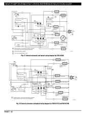
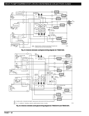
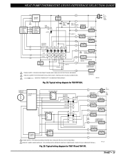
...COOL CHANGEOVER VALVE O COOL C. Typical wiring diagram for T8611G1004 and T8611G1103. L1 (HOT) L2 1 70-6627 • 21 HT. O. O. HT. LED (GREEN) L HEAT 2 MONITOR W2 AUX. PROVIDE DISCONNECT MEANS AND OVERLOAD PROTECTION AS REQUIRED. 2 DENOTES THERMOSTAT TO SUBBASE INTERCONNECT. HT. B HEAT CHANGEOVER VALVE HIGH LIMIT HEAT... OF SEPARATE TRANSFORMER M6020A Fig. 26. HEAT OFF AUTO COOL C. RELAY FAN RELAY G SYSTEM SWITCH EM. HEAT PUMP THERMOSTAT CROSS REFERENCE/SELECTION GUIDE 2 POWER SUPPLY THERMOSTAT LOGIC CIRCUIT SUBBASE LOGIC/ CONTROL CIRCUIT FAN...
...COOL CHANGEOVER VALVE O COOL C. Typical wiring diagram for T8611G1004 and T8611G1103. L1 (HOT) L2 1 70-6627 • 21 HT. O. O. HT. LED (GREEN) L HEAT 2 MONITOR W2 AUX. PROVIDE DISCONNECT MEANS AND OVERLOAD PROTECTION AS REQUIRED. 2 DENOTES THERMOSTAT TO SUBBASE INTERCONNECT. HT. B HEAT CHANGEOVER VALVE HIGH LIMIT HEAT... OF SEPARATE TRANSFORMER M6020A Fig. 26. HEAT OFF AUTO COOL C. RELAY FAN RELAY G SYSTEM SWITCH EM. HEAT PUMP THERMOSTAT CROSS REFERENCE/SELECTION GUIDE 2 POWER SUPPLY THERMOSTAT LOGIC CIRCUIT SUBBASE LOGIC/ CONTROL CIRCUIT FAN...

User Guide
Page 24
...; 22 HT. O. HEAT CHANGEOVER VALVE B STAGE 1 COMPRESSOR CONTACTOR Y STAGE 2 COMPRESSOR CONTACTOR Y2 COOL 2 X1 2 CHECK LED (YELLOW) X2 L1 (HOT) L2 1 1 POWER SUPPLY. ROUTE INTERCONNECT CABLE AWAY FROM SOURCES OF ELECTRICAL NOISE. LED (GREEN) L MONITOR AUX. Typical wiring diagram for T8611M7008. HT. HT. HT. HT. Fig. 27. HEAT PUMP THERMOSTAT CROSS REFERENCE/SELECTION GUIDE THERMOSTAT LOGIC CIRCUIT POWER...
...; 22 HT. O. HEAT CHANGEOVER VALVE B STAGE 1 COMPRESSOR CONTACTOR Y STAGE 2 COMPRESSOR CONTACTOR Y2 COOL 2 X1 2 CHECK LED (YELLOW) X2 L1 (HOT) L2 1 1 POWER SUPPLY. ROUTE INTERCONNECT CABLE AWAY FROM SOURCES OF ELECTRICAL NOISE. LED (GREEN) L MONITOR AUX. Typical wiring diagram for T8611M7008. HT. HT. HT. HT. Fig. 27. HEAT PUMP THERMOSTAT CROSS REFERENCE/SELECTION GUIDE THERMOSTAT LOGIC CIRCUIT POWER...
User Guide
Page 25
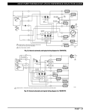
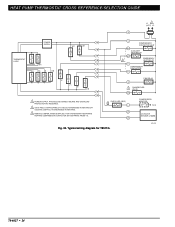
... OVERLOAD PROTECTION AS REQUIRED. 2 REMOVE JUMPER FOR SYSTEM WITH ISOLATED STAGE 1 HEATING AND COOLING CONNECTIONS. 3 DENOTES THERMOSTAT TO SUBBASE INTERCONNECT. PROVIDE DISCONNECT MEANS AND OVERLOAD PROTECTION AS REQUIRED. 2 REMOVE JUMPER, WHEN SUPPLIED, FOR SYSTEMS WITH SEPARATE HEATING COMPRESSOR CONTACTOR (W1 SEPARATE FROM Y). HT. HT. Typical wiring diagram for T8011R and T8411R. 70-6627 • 23 RELAY...
... OVERLOAD PROTECTION AS REQUIRED. 2 REMOVE JUMPER FOR SYSTEM WITH ISOLATED STAGE 1 HEATING AND COOLING CONNECTIONS. 3 DENOTES THERMOSTAT TO SUBBASE INTERCONNECT. PROVIDE DISCONNECT MEANS AND OVERLOAD PROTECTION AS REQUIRED. 2 REMOVE JUMPER, WHEN SUPPLIED, FOR SYSTEMS WITH SEPARATE HEATING COMPRESSOR CONTACTOR (W1 SEPARATE FROM Y). HT. HT. Typical wiring diagram for T8011R and T8411R. 70-6627 • 23 RELAY...
User Guide
Page 26
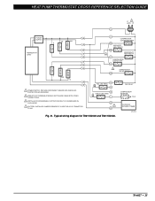
... MEANS AND OVERLOAD PROTECTION AS REQUIRED. 2 O/B IS FIELD CONFIGURABLE TO SELECT ENERGIZED IN HEATING OR COOLING. (DEFAULT IS ENERGIZED IN HEATING). 3 REMOVE JUMPER, WHEN SUPPLIED, FOR SYSTEMS WITH SEPARATE HEATING COMPRESSOR CONTACTOR (W1 SEPARATE FROM Y1). HEAT PUMP THERMOSTAT CROSS REFERENCE/SELECTION GUIDE L1 1 (HOT) L2 R THERMOSTAT LOGIC POWER SUPPLY W2 W1 E Y1 G O/B W2 W1 C COMPRESSOR CONTACTOR...
... MEANS AND OVERLOAD PROTECTION AS REQUIRED. 2 O/B IS FIELD CONFIGURABLE TO SELECT ENERGIZED IN HEATING OR COOLING. (DEFAULT IS ENERGIZED IN HEATING). 3 REMOVE JUMPER, WHEN SUPPLIED, FOR SYSTEMS WITH SEPARATE HEATING COMPRESSOR CONTACTOR (W1 SEPARATE FROM Y1). HEAT PUMP THERMOSTAT CROSS REFERENCE/SELECTION GUIDE L1 1 (HOT) L2 R THERMOSTAT LOGIC POWER SUPPLY W2 W1 E Y1 G O/B W2 W1 C COMPRESSOR CONTACTOR...
User Guide
Page 27
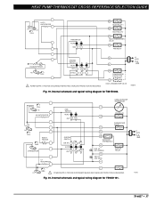
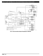
... COOL MODE. 4 FACTORY-INSTALLED JUMPER; REMOVE IF A HEAT RELAY IS CONNECTED TO W1. 3 O/B G FAIL LED (RED) X1 X2 CHECK LED (RED) L OT 2 OT Fig. 31. Typical wiring diagram for T8611G2002 and T8611G2028. PROVIDE DISCONNECT MEANS AND OVERLOAD PROTECTION AS REQUIRED. 2 WIRES TO OT TERMINALS SHOULD NOT SHARE CABLE WITH OTHER CONNECTIONS. 3 INSTALLER CONFIGURABLE. HEAT PUMP THERMOSTAT...
... COOL MODE. 4 FACTORY-INSTALLED JUMPER; REMOVE IF A HEAT RELAY IS CONNECTED TO W1. 3 O/B G FAIL LED (RED) X1 X2 CHECK LED (RED) L OT 2 OT Fig. 31. Typical wiring diagram for T8611G2002 and T8611G2028. PROVIDE DISCONNECT MEANS AND OVERLOAD PROTECTION AS REQUIRED. 2 WIRES TO OT TERMINALS SHOULD NOT SHARE CABLE WITH OTHER CONNECTIONS. 3 INSTALLER CONFIGURABLE. HEAT PUMP THERMOSTAT...
User Guide
Page 35
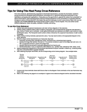
... upgrade desirable. 6. Make a listing of automatic heat/cool changeover and to a Chronotherm® IV thermostat that puts the heat pump to work to the convenience of wiring terminals used for first stage heat and cool, or to match up for first stage heat. - O terminal cool or B terminal heat is required for improved performance and from heat to make identification easier. Connect only those...
... upgrade desirable. 6. Make a listing of automatic heat/cool changeover and to a Chronotherm® IV thermostat that puts the heat pump to work to the convenience of wiring terminals used for first stage heat and cool, or to match up for first stage heat. - O terminal cool or B terminal heat is required for improved performance and from heat to make identification easier. Connect only those...
User Guide
Page 57
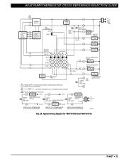
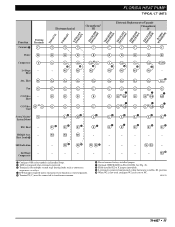
...Stage - W1 W1 W1 W1 W1 W1 W1 - µ W2 W2 W2 W2 W2 W2 W2 W2 Aux. Fan G C/O Valve - Heat C/O Valve or W O Cool System Monitor/ X System Defrost EM. W3 W3 W3 - Compressor - W2 µ ³ Configure O/B (select models) in Em. Ht. position. µ When W2 is wired...X2 to X jumper (provided). ¾ L terminal is powered continuously when thermostat is in Installer Setup. · LED is energized when terminal is powered. » Terminal is for multiple second stage heating loads such as contactors, sequencers, or relays. ¿ E-W2 jumper ...
...Stage - W1 W1 W1 W1 W1 W1 W1 - µ W2 W2 W2 W2 W2 W2 W2 W2 Aux. Fan G C/O Valve - Heat C/O Valve or W O Cool System Monitor/ X System Defrost EM. W3 W3 W3 - Compressor - W2 µ ³ Configure O/B (select models) in Em. Ht. position. µ When W2 is wired...X2 to X jumper (provided). ¾ L terminal is powered continuously when thermostat is in Installer Setup. · LED is energized when terminal is powered. » Terminal is for multiple second stage heating loads such as contactors, sequencers, or relays. ¿ E-W2 jumper ...
User Guide
Page 121
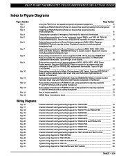
... 6 Installing an R8222B Switching Relay on heat pumps requiring heating mode changeover. 8 Installing an R8222B Switching Relay on heat pumps requiring cooling mode changeover...8 Changing fan operation in heat pump applications requiring separate Y1 and W1 terminals with a heating changeover 12 Relay wiring connections for PC8900 in emergency heat mode for electronic thermostats 9 Relay wiring connections for Carrier equipment (typical...
... 6 Installing an R8222B Switching Relay on heat pumps requiring heating mode changeover. 8 Installing an R8222B Switching Relay on heat pumps requiring cooling mode changeover...8 Changing fan operation in heat pump applications requiring separate Y1 and W1 terminals with a heating changeover 12 Relay wiring connections for PC8900 in emergency heat mode for electronic thermostats 9 Relay wiring connections for Carrier equipment (typical...


