Installation Instructions
Page 2
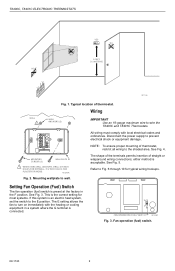
...is the correct setting for typical wiring hookups. This is an electric heat system, set the switch to the shaded area. Wiring WALL 1 WALL ANCHORS (2) IMPORTANT Use an 18-gauge maximum wire to turn on immediately with local electrical codes and ordinances. Fan operation (fuel... All wiring must comply with the heating or cooling equipment in the F position. See Fig. 5. Setting Fan Operation (Fuel) Switch The fan operation (fuel) switch is preset at the factory in a system where the G terminal is acceptable. T8400C, T8401C ELECTRONIC THERMOSTATS YES NO NO 5 FEET [1.5 ...
...is the correct setting for typical wiring hookups. This is an electric heat system, set the switch to the shaded area. Wiring WALL 1 WALL ANCHORS (2) IMPORTANT Use an 18-gauge maximum wire to turn on immediately with local electrical codes and ordinances. Fan operation (fuel... All wiring must comply with the heating or cooling equipment in the F position. See Fig. 5. Setting Fan Operation (Fuel) Switch The fan operation (fuel) switch is preset at the factory in a system where the G terminal is acceptable. T8400C, T8401C ELECTRONIC THERMOSTATS YES NO NO 5 FEET [1.5 ...
Installation Instructions
Page 4
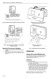
...manually by the heating equipment and may start a few minutes after the heating equipment turns on (on most homes. Mounting Thermostat to latch. Swing down the thermostat and press the lower edge of T8401C in heat-cool system. ...heating equipment. Auto: Normal setting for improved air circulation and air quality. PROVIDE DISCONNECT MEANS AND OVERLOAD PROTECTION AS REQUIRED. M14677A Fig. 11. When using the switches located at the top of the thermostat case. T8400C, T8401C ELECTRONIC THERMOSTATS G C R W B Y O 1 L1 (HOT) 24V L2 TRANSFORMER HEAT...
...manually by the heating equipment and may start a few minutes after the heating equipment turns on (on most homes. Mounting Thermostat to latch. Swing down the thermostat and press the lower edge of T8401C in heat-cool system. ...heating equipment. Auto: Normal setting for improved air circulation and air quality. PROVIDE DISCONNECT MEANS AND OVERLOAD PROTECTION AS REQUIRED. M14677A Fig. 11. When using the switches located at the top of the thermostat case. T8400C, T8401C ELECTRONIC THERMOSTATS G C R W B Y O 1 L1 (HOT) 24V L2 TRANSFORMER HEAT...
Installation Instructions
Page 5
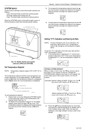
...INCREASE SETTING DECREASE SETTING T8400C, T8401C ELECTRONIC THERMOSTATS 3. M14682 Set Room AuFtAoNOn FAN SWITCH CoSoYl SOTffEMHeat M14678A Fig. 12. Set Temperature Setpoint NOTE: Temperature setpoint range is in steps 2 and 3 only, the ▼ key can be used to turn heat or cool outputs on the digital ...-digit software revision code is displayed for more than one second to light all segments on the digital display. Heat: The thermostat controls the heating system. Each press changes the setpoint one degree; Change the SYSTEM switch setting to the desired mode. Each press...
...INCREASE SETTING DECREASE SETTING T8400C, T8401C ELECTRONIC THERMOSTATS 3. M14682 Set Room AuFtAoNOn FAN SWITCH CoSoYl SOTffEMHeat M14678A Fig. 12. Set Temperature Setpoint NOTE: Temperature setpoint range is in steps 2 and 3 only, the ▼ key can be used to turn heat or cool outputs on the digital ...-digit software revision code is displayed for more than one second to light all segments on the digital display. Heat: The thermostat controls the heating system. Each press changes the setpoint one degree; Change the SYSTEM switch setting to the desired mode. Each press...
Installation Instructions
Page 6
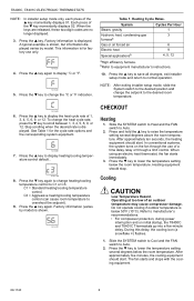
...For compressor protection, during power interruption and on the fan through the use only. In conventional systems, the system turns on initial startup, the T8400C and T8401C Thermostats go into a five-minute delay. Operating at too low of 1, 3, 4, 5, 6, 9, or 12. ...position and change heating/cooling temperature control to the desired room temperature. M18420 CHECKOUT Heating 1. Press the ▼ key to display heating/cooling temperature control default.. During this delay, the cooling icon (a snowflake ❄) flashes. 1. T8400C, T8401C ELECTRONIC THERMOSTATS NOTE: In ...
...For compressor protection, during power interruption and on the fan through the use only. In conventional systems, the system turns on initial startup, the T8400C and T8401C Thermostats go into a five-minute delay. Operating at too low of 1, 3, 4, 5, 6, 9, or 12. ...position and change heating/cooling temperature control to the desired room temperature. M18420 CHECKOUT Heating 1. Press the ▼ key to display heating/cooling temperature control default.. During this delay, the cooling icon (a snowflake ❄) flashes. 1. T8400C, T8401C ELECTRONIC THERMOSTATS NOTE: In ...
Installation Instructions
Page 7
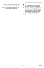
... To bypass the five-minute delay, see the Optional System Checkout section. T8400C, T8401C ELECTRONIC THERMOSTATS Fan 1. 3. Press the ▲ key to the thermostat. 7 69-1740 When using an electric heat thermostat, the fan starts and stops with the cooling equipment. Cooling system should run continuously. ... responds correctly to raise the temperature setting above the room temperature. In heating, the fan is controlled directly by the heating equipment and may start a few minutes after the heating equipment turns on (on most systems). The fan should shut down. Slide the ...
... To bypass the five-minute delay, see the Optional System Checkout section. T8400C, T8401C ELECTRONIC THERMOSTATS Fan 1. 3. Press the ▲ key to the thermostat. 7 69-1740 When using an electric heat thermostat, the fan starts and stops with the cooling equipment. Cooling system should run continuously. ... responds correctly to raise the temperature setting above the room temperature. In heating, the fan is controlled directly by the heating equipment and may start a few minutes after the heating equipment turns on (on most systems). The fan should shut down. Slide the ...


