Owner's Manual
Page 1
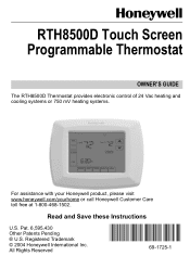
Read and Save these Instructions U.S. Pat. 6,595,430 Other Patents Pending ® U.S. Registered Trademark © 2004 Honeywell International Inc. All Rights Reserved 69-1725-1 RTH8500D Touch Screen Programmable Thermostat OWNER'S GUIDE The RTH8500D Thermostat provides electronic control of 24 Vac heating and cooling systems or 750 mV heating systems. For assistance with your Honeywell product, please visit www.honeywell.com/yourhome or call Honeywell Customer Care toll free at 1-800-468-1502.
Read and Save these Instructions U.S. Pat. 6,595,430 Other Patents Pending ® U.S. Registered Trademark © 2004 Honeywell International Inc. All Rights Reserved 69-1725-1 RTH8500D Touch Screen Programmable Thermostat OWNER'S GUIDE The RTH8500D Thermostat provides electronic control of 24 Vac heating and cooling systems or 750 mV heating systems. For assistance with your Honeywell product, please visit www.honeywell.com/yourhome or call Honeywell Customer Care toll free at 1-800-468-1502.
Owner's Manual
Page 2
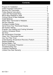
... Wallplate to Wall 11 Connect Wires to New Wallplate 15 Install Batteries 22 Attach New Thermostat to Wallplate 23 Set the Calendar 24 Configure Installer Setup 26 Get to Know Your Thermostat Display 38 Set System Setting 40 Program Your Heating and Cooling Schedule 42 Cancel a ...Schedule Period 46 Set Time 47 Set Temperature Overrides 48 Clean Your Thermostat Screen 51 Use Your Filter Timer 52 Understanding Temperature Recovery Feature 53 Replace Batteries 54 Review Battery Tips 57 Built-in Compressor Protection...
... Wallplate to Wall 11 Connect Wires to New Wallplate 15 Install Batteries 22 Attach New Thermostat to Wallplate 23 Set the Calendar 24 Configure Installer Setup 26 Get to Know Your Thermostat Display 38 Set System Setting 40 Program Your Heating and Cooling Schedule 42 Cancel a ...Schedule Period 46 Set Time 47 Set Temperature Overrides 48 Clean Your Thermostat Screen 51 Use Your Filter Timer 52 Understanding Temperature Recovery Feature 53 Replace Batteries 54 Review Battery Tips 57 Built-in Compressor Protection...
Owner's Manual
Page 3
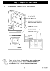
...W1 W1 W2 W2 W3 W3 X X X1 X2 Y Y1 69-0823EFS 5-03 • yourhome M22200 If any of the corresponding letter on your old thermostat wire with the terminal of the items shown above are included: Inside Set OWNER'S GUIDE Inside Set To Read and save these instructions WALLPLATE...'S GUIDE WIRE LABELS CAUTION CARD CAUTION TURN OFF POWER to the store. 3 69-1725-1 Check that the following items are missing, call Honeywell Customer Care at 1-800-468-1502 before returning the thermostat to system at the furnace, or at the fuse/circuit breaker panel before you begin. Step 1.
...W1 W1 W2 W2 W3 W3 X X X1 X2 Y Y1 69-0823EFS 5-03 • yourhome M22200 If any of the corresponding letter on your old thermostat wire with the terminal of the items shown above are included: Inside Set OWNER'S GUIDE Inside Set To Read and save these instructions WALLPLATE...'S GUIDE WIRE LABELS CAUTION CARD CAUTION TURN OFF POWER to the store. 3 69-1725-1 Check that the following items are missing, call Honeywell Customer Care at 1-800-468-1502 before returning the thermostat to system at the furnace, or at the fuse/circuit breaker panel before you begin. Step 1.

Owner's Manual
Page 5
Step 2. Follow Important Instructions 1. OLD THERMOSTAT YELLOW WHITE Y W RED G GREEN RC R ORANGE ! Do not connect the wires to the new thermostat based on wire color because damage can occur to your old thermostat. M22034 5 69-1725-1 DO NOT WIRE NEW THERMOSTAT BASED ON WIRE COLOR. These Installation Instructions explain later how to use the enclosed wire labels to correctly mark the wires connected to the heating and/or cooling system.
Step 2. Follow Important Instructions 1. OLD THERMOSTAT YELLOW WHITE Y W RED G GREEN RC R ORANGE ! Do not connect the wires to the new thermostat based on wire color because damage can occur to your old thermostat. M22034 5 69-1725-1 DO NOT WIRE NEW THERMOSTAT BASED ON WIRE COLOR. These Installation Instructions explain later how to use the enclosed wire labels to correctly mark the wires connected to the heating and/or cooling system.

Owner's Manual
Page 6
... off power at the heating and/or cooling system or fuse/circuit breaker panel. 2. Y G C OLD THERMOSTAT WALLPLATE W THERMOSTAT R COVER .2.18 .9 .7 .5 L O .25 N GE R .4 .3 M22036 MERCURY NOTICE If you are replacing a thermostat that contains mercury in a sealed tube, do not place your local waste management authority for instructions regarding recycling and the proper disposal of...
... off power at the heating and/or cooling system or fuse/circuit breaker panel. 2. Y G C OLD THERMOSTAT WALLPLATE W THERMOSTAT R COVER .2.18 .9 .7 .5 L O .25 N GE R .4 .3 M22036 MERCURY NOTICE If you are replacing a thermostat that contains mercury in a sealed tube, do not place your local waste management authority for instructions regarding recycling and the proper disposal of...

Owner's Manual
Page 7
Step 4. Follow Special Instructions 1. Wrap the bare end of each other or any other wires. 3. OLD THERMOSTAT Y G C C W R LETTER DESIGNATION SCREW TERMINAL WIRE WIRE HOLE DO NOT CONNECT TO NEW THERMOSTAT M22201 7 69-1725-1 Make sure they do not connect them to your new thermostat. 2. Disconnect the C and/or C1 wires. If you have two C and/or C1 wires connected to your old thermostat, do not touch each C and/or C1 wire with electrical tape.
Step 4. Follow Special Instructions 1. Wrap the bare end of each other or any other wires. 3. OLD THERMOSTAT Y G C C W R LETTER DESIGNATION SCREW TERMINAL WIRE WIRE HOLE DO NOT CONNECT TO NEW THERMOSTAT M22201 7 69-1725-1 Make sure they do not connect them to your new thermostat. 2. Disconnect the C and/or C1 wires. If you have two C and/or C1 wires connected to your old thermostat, do not touch each C and/or C1 wire with electrical tape.

Owner's Manual
Page 8
Step 4. Follow Special Instructions (Cont) 4. OLD THERMOSTAT Y G C W R LETTER DESIGNATION SCREW TERMINAL WIRE WIRE HOLE CONNECT TO THE "C" ON THE NEW THERMOSTAT M22223 69-1725-1 8 Visit www.honeywell.com/yourhome or call Honeywell Customer Care at 1-800-468-1502 before returning the thermostat to C on the new thermostat. If you have only one C and/or C1 wire connected to your old thermostat, connect this wire to the store.
Step 4. Follow Special Instructions (Cont) 4. OLD THERMOSTAT Y G C W R LETTER DESIGNATION SCREW TERMINAL WIRE WIRE HOLE CONNECT TO THE "C" ON THE NEW THERMOSTAT M22223 69-1725-1 8 Visit www.honeywell.com/yourhome or call Honeywell Customer Care at 1-800-468-1502 before returning the thermostat to C on the new thermostat. If you have only one C and/or C1 wire connected to your old thermostat, connect this wire to the store.

Owner's Manual
Page 9
Follow Special Instructions (Cont) 5. OLD THERMOSTAT Y G RC W R LETTER DESIGNATION SCREW TERMINAL WIRE WIRE HOLE WIRES NOT CONNECTED - Wrap the end of the wires that are not connected with electrical tape. Step 4. DO NOT CONNECT TO NEW THERMOSTAT M22040 9 69-1725-1 If you find any wires not connected to your old thermostat, do not connect them to your new thermostat. 6.
Follow Special Instructions (Cont) 5. OLD THERMOSTAT Y G RC W R LETTER DESIGNATION SCREW TERMINAL WIRE WIRE HOLE WIRES NOT CONNECTED - Wrap the end of the wires that are not connected with electrical tape. Step 4. DO NOT CONNECT TO NEW THERMOSTAT M22040 9 69-1725-1 If you find any wires not connected to your old thermostat, do not connect them to your new thermostat. 6.

Owner's Manual
Page 10
... 69-1725-1 10 Do not allow the wires to the wire labels. OLD THERMOSTAT W Y RC G Y G RC W R R WIRE LABEL LETTER DESIGNATION SCREW TERMINAL WIRE WIRE HOLE M22039 When connecting the wires to the new thermostat, refer to fall into the wall opening after the wires are disconnected. 2. Do... not connect wires to wrap a wire label around each wire, use the enclosed wire labels to your new thermostat based on the color of the old thermostat from the wall. Label Old Thermostat Wires 1. As you disconnect each wire that matches the letter designation. Step 5.
... 69-1725-1 10 Do not allow the wires to the wire labels. OLD THERMOSTAT W Y RC G Y G RC W R R WIRE LABEL LETTER DESIGNATION SCREW TERMINAL WIRE WIRE HOLE M22039 When connecting the wires to the new thermostat, refer to fall into the wall opening after the wires are disconnected. 2. Do... not connect wires to wrap a wire label around each wire, use the enclosed wire labels to your new thermostat based on the color of the old thermostat from the wall. Label Old Thermostat Wires 1. As you disconnect each wire that matches the letter designation. Step 5.
Owner's Manual
Page 11
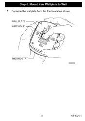
Step 6. Mount New Wallplate to Wall 1. Separate the wallplate from the thermostat as shown. WALLPLATE WIRE HOLE THERMOSTAT M22202 11 69-1725-1
Step 6. Mount New Wallplate to Wall 1. Separate the wallplate from the thermostat as shown. WALLPLATE WIRE HOLE THERMOSTAT M22202 11 69-1725-1

Owner's Manual
Page 15
If you have a standard heating and/or cooling system, use the HEAT PUMP letter designations to wire the new thermostat. WALLPLATE METAL JUMPER WIRE TERMINAL BLOCK SCREW TERMINALS LETTER DESIGNATIONS RC R W Y G C M22206 3. Select the correct letter designations to the letter designations on page 29 to ...
If you have a standard heating and/or cooling system, use the HEAT PUMP letter designations to wire the new thermostat. WALLPLATE METAL JUMPER WIRE TERMINAL BLOCK SCREW TERMINALS LETTER DESIGNATIONS RC R W Y G C M22206 3. Select the correct letter designations to the letter designations on page 29 to ...

Owner's Manual
Page 17
Use the information on the new thermostat the labeled wires 1 RC 1 R RC or R R or RH, 4, V W or W1, H W Y or Y1, M Y G or F G C or C1, X, B C Y2 Y2 W2 W2 2 2 34 M22208 Do not connect more ... referenced in the numbered triangles above. Use the information below if you are wiring a CONVENTIONAL System. These numbered notes appear on your old and new thermostats. CONVENTIONAL Possible letter letter designations designations on on page 20 if you are wiring a Heat Pump System. Be sure to each terminal. Connect Wires to...
Use the information on the new thermostat the labeled wires 1 RC 1 R RC or R R or RH, 4, V W or W1, H W Y or Y1, M Y G or F G C or C1, X, B C Y2 Y2 W2 W2 2 2 34 M22208 Do not connect more ... referenced in the numbered triangles above. Use the information below if you are wiring a CONVENTIONAL System. These numbered notes appear on your old and new thermostats. CONVENTIONAL Possible letter letter designations designations on on page 20 if you are wiring a Heat Pump System. Be sure to each terminal. Connect Wires to...

Owner's Manual
Page 18
... wire in place if only one C and/or C1 wire was connected to the old thermostat, the wire should be connected on the new thermostat. 2 If wires were connected to both R and RH terminals on the new thermostat. Step 7. M22246 69-1725-1 18 Wrap the bare end of the terminals, RC or R,... will be connected to both RC and R on the new thermostat, remove metal jumper wire between RC and R on the new thermostat. Connect Wires to New Wallplate (Cont) NOTES FOR CONVENTIONAL HEATING AND COOLING SYSTEMS 1 If wires will be connected to the...
... wire in place if only one C and/or C1 wire was connected to the old thermostat, the wire should be connected on the new thermostat. 2 If wires were connected to both R and RH terminals on the new thermostat. Step 7. M22246 69-1725-1 18 Wrap the bare end of the terminals, RC or R,... will be connected to both RC and R on the new thermostat, remove metal jumper wire between RC and R on the new thermostat. Connect Wires to New Wallplate (Cont) NOTES FOR CONVENTIONAL HEATING AND COOLING SYSTEMS 1 If wires will be connected to the...
Owner's Manual
Page 19
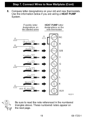
Compare letter designations on the next page. 19 69-1725-1 These numbered notes appear on your old and new thermostats. Use the information below if you are wiring a HEAT PUMP System. Connect Wires to read the note referenced in the numbered triangles above. Step 7. Possible letter designations on the labeled wires HEAT PUMP letter designations on the new thermostat 1 2 VR or V or R 3 H or B, O Y1 or M or Y F or G 3 X or B, C F or L X2 or X, E 4 AUX, W1, W or W2 RC R O/B Y G C L E AUX M22210 Be sure to New Wallplate (Cont) 8.
Compare letter designations on the next page. 19 69-1725-1 These numbered notes appear on your old and new thermostats. Use the information below if you are wiring a HEAT PUMP System. Connect Wires to read the note referenced in the numbered triangles above. Step 7. Possible letter designations on the labeled wires HEAT PUMP letter designations on the new thermostat 1 2 VR or V or R 3 H or B, O Y1 or M or Y F or G 3 X or B, C F or L X2 or X, E 4 AUX, W1, W or W2 RC R O/B Y G C L E AUX M22210 Be sure to New Wallplate (Cont) 8.

Owner's Manual
Page 20
If another wire is already matched to the C, contact Honeywell. 4 If the old thermostat had separate wires on the new thermostat. Call your local heating and cooling contractor for assistance. M22245 69-1725-1 20 Call your local heating and cooling contractor for assistance. 3 If the old thermostat had wires on both the V and VR, some... to attach the B wire to New Wallplate (Cont) NOTES FOR HEAT PUMP SYSTEMS 1 Leave metal jumper wire between RC and R in place. 2 If the old thermostat had wires on W1, Y1 and W2, some system modification is required.
If another wire is already matched to the C, contact Honeywell. 4 If the old thermostat had separate wires on the new thermostat. Call your local heating and cooling contractor for assistance. M22245 69-1725-1 20 Call your local heating and cooling contractor for assistance. 3 If the old thermostat had wires on both the V and VR, some... to attach the B wire to New Wallplate (Cont) NOTES FOR HEAT PUMP SYSTEMS 1 Leave metal jumper wire between RC and R in place. 2 If the old thermostat had wires on W1, Y1 and W2, some system modification is required.
Owner's Manual
Page 22
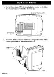
BACK OF THERMOSTAT ++ + BATTERIES (3) M22212 2. Remove the tab labeled "Remove during installation" in the lower right corner of the thermostat as marked on the back of the thermostat back. Install Batteries 1. Step 8. REMOVE TAB REMOVE DURING INSTALLATION REMOVE DURING INSTALLATION 69-1725-1 M19920 22 Install three fresh AAA alkaline batteries on the thermostat.
BACK OF THERMOSTAT ++ + BATTERIES (3) M22212 2. Remove the tab labeled "Remove during installation" in the lower right corner of the thermostat as marked on the back of the thermostat back. Install Batteries 1. Step 8. REMOVE TAB REMOVE DURING INSTALLATION REMOVE DURING INSTALLATION 69-1725-1 M19920 22 Install three fresh AAA alkaline batteries on the thermostat.
Owner's Manual
Page 23
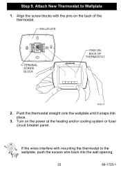
Align the screw blocks with mounting the thermostat to Wallplate 1. Turn on the back of the thermostat. If the wires interfere with the pins on the power at the heating and/or cooling system or fuse/ circuit breaker panel. WALLPLATE TERMINAL SCREW BLOCK PINS ON BACK OF THERMOSTAT M22213 2. Push the thermostat straight onto the wallplate until it snaps into the wall opening. 23 69-1725-1 Step 9. Attach New Thermostat to the wallplate, push the excess wire back into place. 3.
Align the screw blocks with mounting the thermostat to Wallplate 1. Turn on the back of the thermostat. If the wires interfere with the pins on the power at the heating and/or cooling system or fuse/ circuit breaker panel. WALLPLATE TERMINAL SCREW BLOCK PINS ON BACK OF THERMOSTAT M22213 2. Push the thermostat straight onto the wallplate until it snaps into the wall opening. 23 69-1725-1 Step 9. Attach New Thermostat to the wallplate, push the excess wire back into place. 3.
Owner's Manual
Page 24
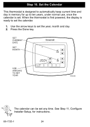
SET CURRENT DATE SET MONTH MON TUE WED THU FRI DONE USE ARROWS TO SET YEAR M22226 The calendar can be set the year, month and day. 2. Step 10. Use the arrow keys to set any time. When the thermostat is first powered, the display is ready to automatically keep current time and day in memory for instructions. 69-1725-1 24 See Step 11, Configure Installer Setup, for up to ten years, under normal use, once the calendar is designed to set . Press the Done key. Set the Calendar This thermostat is set the calendar. 1.
SET CURRENT DATE SET MONTH MON TUE WED THU FRI DONE USE ARROWS TO SET YEAR M22226 The calendar can be set the year, month and day. 2. Step 10. Use the arrow keys to set any time. When the thermostat is first powered, the display is ready to automatically keep current time and day in memory for instructions. 69-1725-1 24 See Step 11, Configure Installer Setup, for up to ten years, under normal use, once the calendar is designed to set . Press the Done key. Set the Calendar This thermostat is set the calendar. 1.
Owner's Manual
Page 26
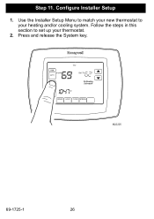
Press and release the System key. Step 11. Configure Installer Setup 1. Use the Installer Setup Menu to match your new thermostat to set up your heating and/or cooling system. FAN ON Inside AUTO THU Set To SYSTEM EM HEAT OFF COOL Following Schedule AM SCHED HOLD CLOCK SCREEN M22225 69-1725-1 26 Follow the steps in this section to your thermostat. 2.
Press and release the System key. Step 11. Configure Installer Setup 1. Use the Installer Setup Menu to match your new thermostat to set up your heating and/or cooling system. FAN ON Inside AUTO THU Set To SYSTEM EM HEAT OFF COOL Following Schedule AM SCHED HOLD CLOCK SCREEN M22225 69-1725-1 26 Follow the steps in this section to your thermostat. 2.
Owner's Manual
Page 27
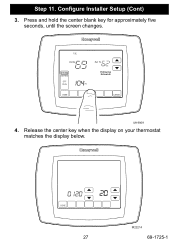
Press and hold the center blank key for approximately five seconds, until the screen changes. Release the center key when the display on your thermostat matches the display below. MON WED THU FRI SAT SUN DONE 27 M22214 69-1725-1 TUE CHANGE FILTER UV LAMP HUMIDIFIER PAD Inside Set To SYSTEM EM HEAT OFF COOL Following Schedule PM DONE CANCEL M19969 4. Step 11. Configure Installer Setup (Cont) 3.
Press and hold the center blank key for approximately five seconds, until the screen changes. Release the center key when the display on your thermostat matches the display below. MON WED THU FRI SAT SUN DONE 27 M22214 69-1725-1 TUE CHANGE FILTER UV LAMP HUMIDIFIER PAD Inside Set To SYSTEM EM HEAT OFF COOL Following Schedule PM DONE CANCEL M19969 4. Step 11. Configure Installer Setup (Cont) 3.


