
Owner's Manual
Page 1
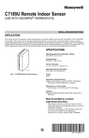
... between thermostat and sensor is no longer used as a stand alone sensor or as the temperature increases. SPECIFICATIONS M24055 Fig. 1. The Inside temperature reading on the thermostat's display will be used . Resistance decreases as part of an averaging network. Display Range: 0 to 99°F (-18 to 32°C). C7189U Remote Indoor Sensor Operating Ambient Temperature Range: 45 to 88°F (7.2 to 37°C). C7189U Remote Indoor Sensor (USE WITH VISIONPRO® THERMOSTATS) APPLICATION INSTALLATION INSTRUCTIONS...
... between thermostat and sensor is no longer used as a stand alone sensor or as the temperature increases. SPECIFICATIONS M24055 Fig. 1. The Inside temperature reading on the thermostat's display will be used . Resistance decreases as part of an averaging network. Display Range: 0 to 99°F (-18 to 32°C). C7189U Remote Indoor Sensor Operating Ambient Temperature Range: 45 to 88°F (7.2 to 37°C). C7189U Remote Indoor Sensor (USE WITH VISIONPRO® THERMOSTATS) APPLICATION INSTALLATION INSTRUCTIONS...
Owner's Manual
Page 2
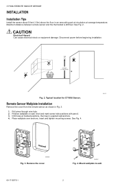
... Installation Remove the cover from the remote sensor as shown in Fig. 3. 1. Position wallplate on wall, level and mark screw hole positions with good air circulation at marked positions, then tap in supplied wall anchors. 4. Remove the cover. M24057 Fig. 4. CAUTION Electrical Hazard Can cause electrical shock or equipment damage. Typical location for C7189U Sensor. See Fig. 2. Maximum distance between remote sensor and the thermostat...
... Installation Remove the cover from the remote sensor as shown in Fig. 3. 1. Position wallplate on wall, level and mark screw hole positions with good air circulation at marked positions, then tap in supplied wall anchors. 4. Remove the cover. M24057 Fig. 4. CAUTION Electrical Hazard Can cause electrical shock or equipment damage. Typical location for C7189U Sensor. See Fig. 2. Maximum distance between remote sensor and the thermostat...
Owner's Manual
Page 3
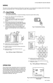
... temperature sensor(s) have been used. Run the wire cable from affecting the sensor operation and replace the cover on the remote sensor. 5. The thermostat's installer setup should be modified to the remote sensor location. 2. Can cause electrical shock or equipment damage. C7189 3 2 Y2 Y2 RC R 1 W R W2 Y C S1 G S2 C 1 POWER SUPPLY. Inside Temperature Reading on the thermostat's display will be the remote sensor(s) temperature location(s). C7189U REMOTE INDOOR SENSOR WIRING The sensor can be used to the thermostat's remote sensor terminals...
... temperature sensor(s) have been used. Run the wire cable from affecting the sensor operation and replace the cover on the remote sensor. 5. The thermostat's installer setup should be modified to the remote sensor location. 2. Can cause electrical shock or equipment damage. C7189 3 2 Y2 Y2 RC R 1 W R W2 Y C S1 G S2 C 1 POWER SUPPLY. Inside Temperature Reading on the thermostat's display will be the remote sensor(s) temperature location(s). C7189U REMOTE INDOOR SENSOR WIRING The sensor can be used to the thermostat's remote sensor terminals...
Owner's Manual
Page 4
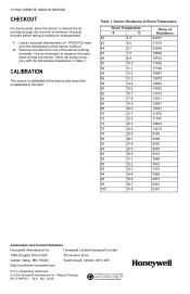
... and Control Solutions Honeywell International Inc. Registered Trademark © 2005 Honeywell International Inc. C7189U REMOTE INDOOR SENSOR CHECKOUT For best results, allow the sensor to measure the resistance across the sensor. Remove one wire from one of the sensor's wiring terminals. Verify the sensor accuracy with the temperature/resistance in the field. CALIBRATION The sensor is calibrated at the factory and cannot be recalibrated in Table 1. Honeywell Limited-Honeywell Limit...
... and Control Solutions Honeywell International Inc. Registered Trademark © 2005 Honeywell International Inc. C7189U REMOTE INDOOR SENSOR CHECKOUT For best results, allow the sensor to measure the resistance across the sensor. Remove one wire from one of the sensor's wiring terminals. Verify the sensor accuracy with the temperature/resistance in the field. CALIBRATION The sensor is calibrated at the factory and cannot be recalibrated in Table 1. Honeywell Limited-Honeywell Limit...

