
Owner's Manual
Page 1
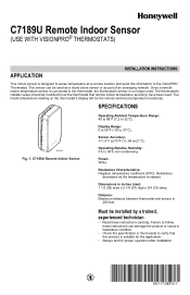
... 95% non-condensing. Once a remote indoor temperature sensor is connected to the thermostat, the thermostat's sensor is no longer used as a stand alone sensor or as the temperature increases. C7189U Remote Indoor Sensor Operating Ambient Temperature Range: 45 to 88°F (7.2 to the VisionPRO Thermostat. C7189U Remote Indoor Sensor (USE WITH VISIONPRO® THERMOSTATS) APPLICATION INSTALLATION INSTRUCTIONS...
... 95% non-condensing. Once a remote indoor temperature sensor is connected to the thermostat, the thermostat's sensor is no longer used as a stand alone sensor or as the temperature increases. C7189U Remote Indoor Sensor Operating Ambient Temperature Range: 45 to 88°F (7.2 to the VisionPRO Thermostat. C7189U Remote Indoor Sensor (USE WITH VISIONPRO® THERMOSTATS) APPLICATION INSTALLATION INSTRUCTIONS...
Owner's Manual
Page 2
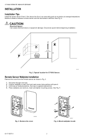
... Fig. 4. See Fig. 2. CAUTION Electrical Hazard Can cause electrical shock or equipment damage. C7189U REMOTE INDOOR SENSOR INSTALLATION Installation Tips Install the sensor about 5 feet (1.5m) above the floor in an area with pencil. 3. See Fig. 4. Typical location for C7189U Sensor. Remove the cover. Place wallplate over anchors, insert and tighten mounting screws. M24056 Fig...
... Fig. 4. See Fig. 2. CAUTION Electrical Hazard Can cause electrical shock or equipment damage. C7189U REMOTE INDOOR SENSOR INSTALLATION Installation Tips Install the sensor about 5 feet (1.5m) above the floor in an area with pencil. 3. See Fig. 4. Typical location for C7189U Sensor. Remove the cover. Place wallplate over anchors, insert and tighten mounting screws. M24056 Fig...
Owner's Manual
Page 3
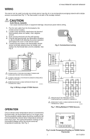
.... 5. The thermostat's installer setup should be the remote sensor(s) temperature location(s). Wiring Multiple C7189U Sensors. . Inside Temperature Reading on the remote sensor. 5. C7189U REMOTE INDOOR SENSOR WIRING The sensor can be used to provide one remote sensor (see Fig. 6) or as a temperature averaging network ...CAUTION ELECTRICAL HAZARD. Connect the two wires to the thermostat, the thermostat's sensor is not part of the average network. M19972A Fig. 6. Wiring a single C7189U Sensor. The thermostat is no longer used. TUE FAN CHANGE FILTER UV LAMP HUMIDIFIER...
.... 5. The thermostat's installer setup should be the remote sensor(s) temperature location(s). Wiring Multiple C7189U Sensors. . Inside Temperature Reading on the remote sensor. 5. C7189U REMOTE INDOOR SENSOR WIRING The sensor can be used to provide one remote sensor (see Fig. 6) or as a temperature averaging network ...CAUTION ELECTRICAL HAZARD. Connect the two wires to the thermostat, the thermostat's sensor is not part of the average network. M19972A Fig. 6. Wiring a single C7189U Sensor. The thermostat is no longer used. TUE FAN CHANGE FILTER UV LAMP HUMIDIFIER...
Owner's Manual
Page 4
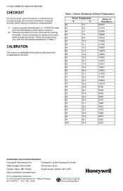
... 14356 13743 13161 12607 12081 11578 11100 10644 10210 9795 9398 9020 8659 8315 7986 7672 7372 7086 6813 6551 6301 Automation and Control Solutions Honeywell International Inc. Table 1. Room Temperature °F °C 40 4.4 42 5.6 44 6.7 46 7.8 48 8.9 50 10.0 52 11.1 54 12.2 ... 92 33.3 94 34.4 96 35.6 98 36.7 100 37.8 Ohms of the sensor's wiring terminals. C7189U REMOTE INDOOR SENSOR CHECKOUT For best results, allow the sensor to measure the resistance across the sensor. Use an ohmmeter to absorb the air moving through the room for a minimum of twenty...
... 14356 13743 13161 12607 12081 11578 11100 10644 10210 9795 9398 9020 8659 8315 7986 7672 7372 7086 6813 6551 6301 Automation and Control Solutions Honeywell International Inc. Table 1. Room Temperature °F °C 40 4.4 42 5.6 44 6.7 46 7.8 48 8.9 50 10.0 52 11.1 54 12.2 ... 92 33.3 94 34.4 96 35.6 98 36.7 100 37.8 Ohms of the sensor's wiring terminals. C7189U REMOTE INDOOR SENSOR CHECKOUT For best results, allow the sensor to measure the resistance across the sensor. Use an ohmmeter to absorb the air moving through the room for a minimum of twenty...


