
Owner's Manual
Page 1
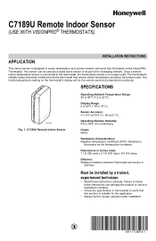
... Characteristics: Negative temperature coefficient (NTC). Resistance decreases as part of an averaging network. C7189U Remote Indoor Sensor Operating Ambient Temperature Range: 45 to 88°F (7.2 to 37°C). C7189U Remote Indoor Sensor (USE WITH VISIONPRO® THERMOSTATS) APPLICATION INSTALLATION INSTRUCTIONS This indoor sensor is 200 feet. This sensor can damage the product or...
... Characteristics: Negative temperature coefficient (NTC). Resistance decreases as part of an averaging network. C7189U Remote Indoor Sensor Operating Ambient Temperature Range: 45 to 88°F (7.2 to 37°C). C7189U Remote Indoor Sensor (USE WITH VISIONPRO® THERMOSTATS) APPLICATION INSTALLATION INSTRUCTIONS This indoor sensor is 200 feet. This sensor can damage the product or...
Owner's Manual
Page 2
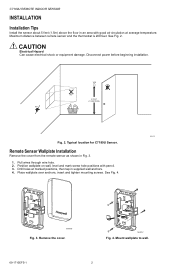
... from the remote sensor as shown in Fig. 3. 1. Place wallplate over anchors, insert and tighten mounting screws. M24057 Fig. 4. Disconnect power before beginning installation. C7189U REMOTE INDOOR SENSOR INSTALLATION Installation Tips Install the sensor about 5 feet (1.5m) above the floor in an area with pencil. 3. Maximum distance between remote sensor and the thermostat is 200...
... from the remote sensor as shown in Fig. 3. 1. Place wallplate over anchors, insert and tighten mounting screws. M24057 Fig. 4. Disconnect power before beginning installation. C7189U REMOTE INDOOR SENSOR INSTALLATION Installation Tips Install the sensor about 5 feet (1.5m) above the floor in an area with pencil. 3. Maximum distance between remote sensor and the thermostat is 200...
Owner's Manual
Page 3
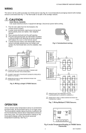
.... 6. Terminal block wiring. C7189 3 2 Y2 Y2 RC R 1 W R W2 Y C S1 G S2 C 1 POWER SUPPLY. The thermostat's installer setup should be modified to tell the thermostat that remote indoor temperature sensor(s) have been used . See Fig. 8. 1 SENSORS MUST BE ARRANGED IN THIS ...To AUTO Heat On SYSTEM Following Schedule HEAT AM SCHED HOLD CLOCK SCREEN MORE M19974 Fig. 8. Disconnect power before wiring. 1. Wiring a single C7189U Sensor. Plug the wall opening . 4. M24116 Fig. 5. M19972A Fig. 6. The thermostat is no longer used . Loosen screw terminals, ...
.... 6. Terminal block wiring. C7189 3 2 Y2 Y2 RC R 1 W R W2 Y C S1 G S2 C 1 POWER SUPPLY. The thermostat's installer setup should be modified to tell the thermostat that remote indoor temperature sensor(s) have been used . See Fig. 8. 1 SENSORS MUST BE ARRANGED IN THIS ...To AUTO Heat On SYSTEM Following Schedule HEAT AM SCHED HOLD CLOCK SCREEN MORE M19974 Fig. 8. Disconnect power before wiring. 1. Wiring a single C7189U Sensor. Plug the wall opening . 4. M24116 Fig. 5. M19972A Fig. 6. The thermostat is no longer used . Loosen screw terminals, ...


