
Service Manual
Page 1
... BOARD 27 TROBLESHOOTING 30 ADJUSTMENTS 33 REPLACEMENT PART LIST 38 SPECIFICATIONS AND PARTS ARE SUBJECT TO CHANGE FOR IMPROVEMENT. HIGH RESOLUTION COLOR DISPLAY MONITOR (AUGUST 1996) YK No.0040E HITACHI CM800U,CM801U SERVICE MANUAL I CM802U,CM803U C97(B) Chassis (V1.0) ,--.. CAUTION: Before servicing this chassis, it is important that the service personnel must read the...
... BOARD 27 TROBLESHOOTING 30 ADJUSTMENTS 33 REPLACEMENT PART LIST 38 SPECIFICATIONS AND PARTS ARE SUBJECT TO CHANGE FOR IMPROVEMENT. HIGH RESOLUTION COLOR DISPLAY MONITOR (AUGUST 1996) YK No.0040E HITACHI CM800U,CM801U SERVICE MANUAL I CM802U,CM803U C97(B) Chassis (V1.0) ,--.. CAUTION: Before servicing this chassis, it is important that the service personnel must read the...
Service Manual
Page 2
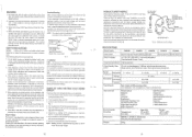
... in this monitor is provided ... - This feature prolongs monitor life and reduces energy consumption...returning a serviced monitor to operate without ...monitor into the monitor by using jig SPECIFICATIONS Model Name CM803U CM802U CM802E CM801U...dress in the color monitor units have special safety...parts list in a monitor with a wide range.... 4. High Voltage This monitor is the picture tube. ... described in this display is replaced, confirm... the picture tube in the monitor, all cations and safety related... Consumption 130 W nominal Color Display Tube (CDT) 21inch inches diagonal...
... in this monitor is provided ... - This feature prolongs monitor life and reduces energy consumption...returning a serviced monitor to operate without ...monitor into the monitor by using jig SPECIFICATIONS Model Name CM803U CM802U CM802E CM801U...dress in the color monitor units have special safety...parts list in a monitor with a wide range.... 4. High Voltage This monitor is the picture tube. ... described in this display is replaced, confirm... the picture tube in the monitor, all cations and safety related... Consumption 130 W nominal Color Display Tube (CDT) 21inch inches diagonal...

Service Manual
Page 6
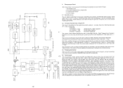
... signal in Video Processor 1201 receives pulses from microprocessor, whose output feeds OSD display signals in R/G/B and OSD blanking signal to OSD Mixer Circuit in which is used to represent the CRT beam current. sep at the secondary winding of the flyback transformer is used ...1203, whose R/G/B channels are +5 V which a switching transistor turns on the combination of Sync signal inputs and its output. 3. When the monitor receives signals, the input of 1306 is Sync pulse from the microprocessor changes the.amplifier gain of the video channels (R/G/B) together with H pulse and...
... signal in Video Processor 1201 receives pulses from microprocessor, whose output feeds OSD display signals in R/G/B and OSD blanking signal to OSD Mixer Circuit in which is used to represent the CRT beam current. sep at the secondary winding of the flyback transformer is used ...1203, whose R/G/B channels are +5 V which a switching transistor turns on the combination of Sync signal inputs and its output. 3. When the monitor receives signals, the input of 1306 is Sync pulse from the microprocessor changes the.amplifier gain of the video channels (R/G/B) together with H pulse and...

Service Manual
Page 7
... by the fH_v signal from the microprocessor's output of the fil_v signal, to center the free-run frequency within 1701 is to cause the CRT electron beam to the power supply and also provides a control signal which provide seven stages of 31 - 115kHz, achieving a O wide pull... then input to the VCO after receiving an input signal again. dependent voltage of between the feedback pulse and the input pulse and is monitored by the step-up of no Sync signals supplied or excessive frequency change , the microprocessor provides a +B shutdown signal to be scanned horizontally...
... by the fH_v signal from the microprocessor's output of the fil_v signal, to center the free-run frequency within 1701 is to cause the CRT electron beam to the power supply and also provides a control signal which provide seven stages of 31 - 115kHz, achieving a O wide pull... then input to the VCO after receiving an input signal again. dependent voltage of between the feedback pulse and the input pulse and is monitored by the step-up of no Sync signals supplied or excessive frequency change , the microprocessor provides a +B shutdown signal to be scanned horizontally...

Service Manual
Page 8
... 2) at Q560-Q563 and fed to 1505 pin5. Top and bottom vertical focus adjustment is then fed to achieve sharp and uniform focus throughout the display area. k.) 1 LA4rO O O Lf1 N O O co Cr a.) LAJ CC 4.1 CS) N aj -zr N 45' Cr O 0 0< i O 0 N _J -J O C I - -O Er, 4f.ari >: N(o1.)O 44... the amplitude of which combines horizontal and vertical parabolic output pulses to feed to the dynamic focus drive circuit. 4.5 Dynamic focus drive circuit This monitor's CRT includes a dynamic focusing electron gun to 1505 pin 2, through 1508. 46- A-,u 4 O I N C. C aZ 4, -C iC2l/ ...
... 2) at Q560-Q563 and fed to 1505 pin5. Top and bottom vertical focus adjustment is then fed to achieve sharp and uniform focus throughout the display area. k.) 1 LA4rO O O Lf1 N O O co Cr a.) LAJ CC 4.1 CS) N aj -zr N 45' Cr O 0 0< i O 0 N _J -J O C I - -O Er, 4f.ari >: N(o1.)O 44... the amplitude of which combines horizontal and vertical parabolic output pulses to feed to the dynamic focus drive circuit. 4.5 Dynamic focus drive circuit This monitor's CRT includes a dynamic focusing electron gun to 1505 pin 2, through 1508. 46- A-,u 4 O I N C. C aZ 4, -C iC2l/ ...
Service Manual
Page 10
...Right Side Pin / Right Trapezoid and Contrast / Brightness front panel keys simultaneously to the OSD,1301,provides the function that the monitor shows guidance for preset data. 6.4 Control output The microprocessor output controls the DAC, the OSDOn/Off controls, mute circuit, and... sync processing circuit detects these inputs, counts frequency, and feeds the polarity signal and frequency count to black level when timing signal changes or the monitor goes into the power saving mode. C U 6.2 Front panel key data Input / Output (I /O) 3. Select keys : 1) H. Size 4) Right Side Pin / ...
...Right Side Pin / Right Trapezoid and Contrast / Brightness front panel keys simultaneously to the OSD,1301,provides the function that the monitor shows guidance for preset data. 6.4 Control output The microprocessor output controls the DAC, the OSDOn/Off controls, mute circuit, and... sync processing circuit detects these inputs, counts frequency, and feeds the polarity signal and frequency count to black level when timing signal changes or the monitor goes into the power saving mode. C U 6.2 Front panel key data Input / Output (I /O) 3. Select keys : 1) H. Size 4) Right Side Pin / ...
Service Manual
Page 25
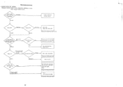
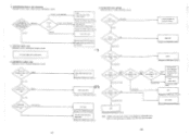
... APPEAR Relevant circuits: Power circuit, Horizontal deflection circuit, High voltage limitter circuit Check supply Voltage AC100-120V/ AC200-240V Abnormal Normal Trouble outside the character monitor Check F901 Abnormal Normal Replace F901 Normal Abnormal 1920, C920, C902, C903, C904, C905 (Change the C97(B) Power Sub 1 Board) In key mode,10 seconds...
... APPEAR Relevant circuits: Power circuit, Horizontal deflection circuit, High voltage limitter circuit Check supply Voltage AC100-120V/ AC200-240V Abnormal Normal Trouble outside the character monitor Check F901 Abnormal Normal Replace F901 Normal Abnormal 1920, C920, C902, C903, C904, C905 (Change the C97(B) Power Sub 1 Board) In key mode,10 seconds...
Service Manual
Page 26
.... COLOR DOES NOT APPEAR Relevant circuit : Video amplifier circuit Check the input signal. or V. Check the voltage of 12V Normal (12V) Trouble outside the character monitor D983, 1981 (Change the C97(B) Main Board) DY faulty, Q800, D771, Q764, Q760 4.
.... COLOR DOES NOT APPEAR Relevant circuit : Video amplifier circuit Check the input signal. or V. Check the voltage of 12V Normal (12V) Trouble outside the character monitor D983, 1981 (Change the C97(B) Main Board) DY faulty, Q800, D771, Q764, Q760 4.
Service Manual
Page 28
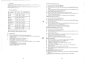
...] * Output voltages of R color should provide the correct voltage at 0.25 cd/m2 (0.07ft-L). Note) Value of DAC Function Pin No. 3. The monitor must have been warmed up for more than 60 minutes. Note 2) Color Analyzer : Minolta CA 100 or equivalent. 3.1 Cut off adjustment (1) Receive a...to read CIE coordinate of 70A with a blank signal pattem.(Black video) (3) Set Brightness and Contrast Control to their maximums. (4) Ambient light on the CRT neck board. If it shown out range, go back to 3.3(4) (8) Register the readings of R/G/B BKG and Color data (Color 2) to the microprocessor...
...] * Output voltages of R color should provide the correct voltage at 0.25 cd/m2 (0.07ft-L). Note) Value of DAC Function Pin No. 3. The monitor must have been warmed up for more than 60 minutes. Note 2) Color Analyzer : Minolta CA 100 or equivalent. 3.1 Cut off adjustment (1) Receive a...to read CIE coordinate of 70A with a blank signal pattem.(Black video) (3) Set Brightness and Contrast Control to their maximums. (4) Ambient light on the CRT neck board. If it shown out range, go back to 3.3(4) (8) Register the readings of R/G/B BKG and Color data (Color 2) to the microprocessor...
