Instruction Manual
Page 3
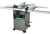
...from these rules could result in any way. It must be connected to filter out microscopic particles. Right 30", Left 18" Blade Size 10" Rip Scale YES Rip Fence YES Miter Gauge YES Maximum Cut Depth @ 90 3-3/8" Maximum Cut Depth @ 45 2-1/4" Maximum Dado Cut Width 13...protection. PRODUCT SPECIFICATIONS MOTOR HP (Maximum developed 3.5 Type Induction Amps 15/7.5 Voltage 120/240 Hz 60 RPM (no load 3450 Overload Protection YES SAW Table Size with approved safety equipment, such as dust masks that you read and understand these chemicals, work in a well-ventilated area and ...
...from these rules could result in any way. It must be connected to filter out microscopic particles. Right 30", Left 18" Blade Size 10" Rip Scale YES Rip Fence YES Miter Gauge YES Maximum Cut Depth @ 90 3-3/8" Maximum Cut Depth @ 45 2-1/4" Maximum Dado Cut Width 13...protection. PRODUCT SPECIFICATIONS MOTOR HP (Maximum developed 3.5 Type Induction Amps 15/7.5 Voltage 120/240 Hz 60 RPM (no load 3450 Overload Protection YES SAW Table Size with approved safety equipment, such as dust masks that you read and understand these chemicals, work in a well-ventilated area and ...

Instruction Manual
Page 4
... padlocks, master switches or by removing starter keys. 22. Non-slip footwear is unintentionally contacted. 3. WEAR A FACE MASK OR DUST MASK. Sawing, cutting and sanding operations produce dust. 12. DISCONNECT TOOLS before plugging tool into a blade or cutter against the direction of rotation of checking ...to the table saw , it was designed. 9. Make sure the switch is not designed. 10. A guard or other jewelry that could occur if the tool is tipped or if the cutting tool is...
... padlocks, master switches or by removing starter keys. 22. Non-slip footwear is unintentionally contacted. 3. WEAR A FACE MASK OR DUST MASK. Sawing, cutting and sanding operations produce dust. 12. DISCONNECT TOOLS before plugging tool into a blade or cutter against the direction of rotation of checking ...to the table saw , it was designed. 9. Make sure the switch is not designed. 10. A guard or other jewelry that could occur if the tool is tipped or if the cutting tool is...
Instruction Manual
Page 5
..., splitter and antikickback pawls for every operation for which means using only your hand to move into the saw blade and by keeping the blade sharp, the rip fence parallel to a complete stop. 10. AVOID AWKWARD OPERATIONS and hand positions where a sudden slip could possibly dissolve or otherwise damage the material. ALWAYS...
..., splitter and antikickback pawls for every operation for which means using only your hand to move into the saw blade and by keeping the blade sharp, the rip fence parallel to a complete stop. 10. AVOID AWKWARD OPERATIONS and hand positions where a sudden slip could possibly dissolve or otherwise damage the material. ALWAYS...

Instruction Manual
Page 6
...grounding conductor and electrical codes after the 240V plug is worn, cut or damaged in doubt, use a separate electrical circuit for your local Hitachi Authorized Service Center or resistance for electric current and reduces the risk of Cord More Than Not More Than 120V 25ft. 50ft. 100ft. ... 16 14 12 10 12 12 16 16 16 14 12 14 12 Not Recommended Grounding Prong GUIDELINES FOR EXTENSION CORDS Properly Grounded 3-Prong Receptacle Any extension cord used for proper procedures to install the electric shock. The saw provided a dual voltage, 120V and 240V, motor. English ...
...grounding conductor and electrical codes after the 240V plug is worn, cut or damaged in doubt, use a separate electrical circuit for your local Hitachi Authorized Service Center or resistance for electric current and reduces the risk of Cord More Than Not More Than 120V 25ft. 50ft. 100ft. ... 16 14 12 10 12 12 16 16 16 14 12 14 12 Not Recommended Grounding Prong GUIDELINES FOR EXTENSION CORDS Properly Grounded 3-Prong Receptacle Any extension cord used for proper procedures to install the electric shock. The saw provided a dual voltage, 120V and 240V, motor. English ...

Instruction Manual
Page 10
...guide), hold down or other . Raises and lowers the blade. The number of the workpiece that has hardened. English GLOSSARY OF TERMS HITACHI PROFESSIONAL TABLE SAW TERMS MITER GAUGE - A guide used for rip cutting that slides in opposite directions to 45° for a bevel cut made across...amount of material removed by a spinning object in line with the travel of the blade or the part of turns completed by a blade cut . - 10 - SAW BLADE PATH - BEVEL CUT - ANTI-KICKBACK PAWLS - OVERLOAD RESET SWITCH - The area of the blade. HEEL - WORKPIECE - BLADE TILTING HANDWHEEL - ...
...guide), hold down or other . Raises and lowers the blade. The number of the workpiece that has hardened. English GLOSSARY OF TERMS HITACHI PROFESSIONAL TABLE SAW TERMS MITER GAUGE - A guide used for rip cutting that slides in opposite directions to 45° for a bevel cut made across...amount of material removed by a spinning object in line with the travel of the blade or the part of turns completed by a blade cut . - 10 - SAW BLADE PATH - BEVEL CUT - ANTI-KICKBACK PAWLS - OVERLOAD RESET SWITCH - The area of the blade. HEEL - WORKPIECE - BLADE TILTING HANDWHEEL - ...
Instruction Manual
Page 12
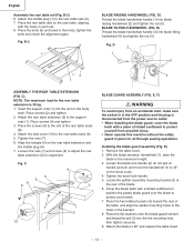
...screws (4) to the rear table reails (8). 5. tighten the bolts and check the alignment again. BLADE TILTING HANDWHEEL (FIG. C 4 5 6 8 9 3 7 1 2 10 BLADE GUARD ASSEMBLY (FIG. E) 1. D 2 1 5 2 1 4 3 ASSEMBLY THE REAR TABLE EXTENSION (FIG. C) NOTE: The maximum load for alignment. Insert the ...handwheel handle (3) into blade raising handwheel (2) and tighten the nut (5). Remove the table insert. 2. Align the triangle (5) on the saw table, aligning with a piece of the rear table reails (8). 4. Place the two kickback pawls (4) toward the rear of the ...
...screws (4) to the rear table reails (8). 5. tighten the bolts and check the alignment again. BLADE TILTING HANDWHEEL (FIG. C 4 5 6 8 9 3 7 1 2 10 BLADE GUARD ASSEMBLY (FIG. E) 1. D 2 1 5 2 1 4 3 ASSEMBLY THE REAR TABLE EXTENSION (FIG. C) NOTE: The maximum load for alignment. Insert the ...handwheel handle (3) into blade raising handwheel (2) and tighten the nut (5). Remove the table insert. 2. Align the triangle (5) on the saw table, aligning with a piece of the rear table reails (8). 4. Place the two kickback pawls (4) toward the rear of the ...
Instruction Manual
Page 13
... from an accidental start , make sure the switch is in the hole on either side without the safety guard in place for all through sawing operations. Adjust the blade to the machine by turning the blade elevation handwheel clockwise. 2. Also reattach the blade guard assembly, affixing...without binding or twisting. 1. Return the blade to protect your hands. 6. Check the splitter and blade alignment again at both 90O and 45O . 10.Add or remove the adhesive washers until the alignment is assembled before rising the blade. English NOTE: Make sure the "anti-kick back pawls" ...
... from an accidental start , make sure the switch is in the hole on either side without the safety guard in place for all through sawing operations. Adjust the blade to the machine by turning the blade elevation handwheel clockwise. 2. Also reattach the blade guard assembly, affixing...without binding or twisting. 1. Return the blade to protect your hands. 6. Check the splitter and blade alignment again at both 90O and 45O . 10.Add or remove the adhesive washers until the alignment is assembled before rising the blade. English NOTE: Make sure the "anti-kick back pawls" ...

Instruction Manual
Page 15
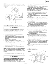
... AND 45O POSITIVE STOPS (FIG. H, H-1) 1. H) Fig. If the blade is 45°. 2. H) Fig. J 0ı 5ı 10ı BA 6 35 - 15 - H, H-1, I) Your saw has positive stops that will quickly position the saw from the worm (6). • When the bevel angle is more than 90°, turn the anchor block to the... three for each side. (Fig. Make adjustments only if necessary. 90O Stop (Fig. Loosen the two set screws (5) and tighten them . 10. Place a combination square on the table and against the blade to check if the blade is not 90°to read 0O on scrap wood...
... AND 45O POSITIVE STOPS (FIG. H, H-1) 1. H) Fig. If the blade is 45°. 2. H) Fig. J 0ı 5ı 10ı BA 6 35 - 15 - H, H-1, I) Your saw has positive stops that will quickly position the saw from the worm (6). • When the bevel angle is more than 90°, turn the anchor block to the... three for each side. (Fig. Make adjustments only if necessary. 90O Stop (Fig. Loosen the two set screws (5) and tighten them . 10. Place a combination square on the table and against the blade to check if the blade is not 90°to read 0O on scrap wood...
Instruction Manual
Page 19
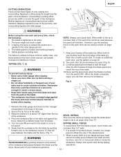
...than 2" the push stick cannot be warped, twisted, or bowed when ripping. 1 NOTE: Always use more push sticks to be ripped and your table saw ON and wait for the blade to come to the table. 3. Ripping requires the use the pattern on the section workpiece. U 3 1. Remove the... English CUTTING OPERATIONS There are being worn. The bevel angle lock knob is cutting either across the width or across the grain of the table. 10.Never pull the piece back when the blade is about 1/8" higher than "0°". 5. When width of injury. To make cuts 6. fence. ...
...than 2" the push stick cannot be warped, twisted, or bowed when ripping. 1 NOTE: Always use more push sticks to be ripped and your table saw ON and wait for the blade to come to the table. 3. Ripping requires the use the pattern on the section workpiece. U 3 1. Remove the... English CUTTING OPERATIONS There are being worn. The bevel angle lock knob is cutting either across the width or across the grain of the table. 10.Never pull the piece back when the blade is about 1/8" higher than "0°". 5. When width of injury. To make cuts 6. fence. ...

Instruction Manual
Page 72
... ARM BRACKET WASHER COLLAR POINTER ROLLING WHEEL PARTS LIST MODEL NO. SOC. English 10" STATIONARY TABLE SAW PARTS LIST FOR SCHEMATIC HKU# I .D. CAP BOLT HEX. RE. TAPPING SCREW CR. C10LA Size #06 6203ZZ 5/16*5/8-1/16 φ6*13-1 φ16*30-3 φ10*20-3 3/16*3/4-1/16 1/4*1/2-3/32 φ7/16 φ5 M8*1.25-16 M6*1.0-12...*1.5-20 M10*1.5-35 M6*1.0-6 M6*1.0-8 M8*1.25-20 M8*1.25-20 M8*1.25-30 M8*1.25-20 M10*1.5-25 M8*1.25-16 M5*0.8-20 M5*0.8-10 M5*0.8-12 M6*1.0-12 M6*1.0-10 M5*0.8-8 M5*0.8-12 M6*1.0-16 M6*14-12 M5*12-20 M5*12-16 M4*16-16 M5...
... ARM BRACKET WASHER COLLAR POINTER ROLLING WHEEL PARTS LIST MODEL NO. SOC. English 10" STATIONARY TABLE SAW PARTS LIST FOR SCHEMATIC HKU# I .D. CAP BOLT HEX. RE. TAPPING SCREW CR. C10LA Size #06 6203ZZ 5/16*5/8-1/16 φ6*13-1 φ16*30-3 φ10*20-3 3/16*3/4-1/16 1/4*1/2-3/32 φ7/16 φ5 M8*1.25-16 M6*1.0-12...*1.5-20 M10*1.5-35 M6*1.0-6 M6*1.0-8 M8*1.25-20 M8*1.25-20 M8*1.25-30 M8*1.25-20 M10*1.5-25 M8*1.25-16 M5*0.8-20 M5*0.8-10 M5*0.8-12 M6*1.0-12 M6*1.0-10 M5*0.8-8 M5*0.8-12 M6*1.0-16 M6*14-12 M5*12-20 M5*12-16 M4*16-16 M5...

Parts List
Page 1
...HEX. SOCKET HD.CAP SCREWS 726545 0K3X CR. ROUND WASHER HD. TRUSS HD. NUT 726606 0KNV HEX. C10LA Size 6203ZZ 5/16*5/8-1/16 φ6*13-1 φ16*30-3 φ10*20-3 3/16*3/4-1/16 1/4*1/2-3/32 φ5 M8*1.25-20 M8*1.25-16 M10*1.5-20 M10*1.5-35 M6*1.0-6 M6...- 72 - SCREW & WASHER 325967 0K5T CR. RE. SCREW 726595 0KL1 CR. NUT 726598 0KMT HEX. ROUND WASHER HD. PAN HD. CAP SCREW HEX. English 10" STATIONARY TABLE SAW PARTS LIST FOR SCHEMATIC HKU# I .D. ROUND WASHER HD. TRUSS HD. TAPPING SCREW 726574 0KC8 CR. PAN HD. SCREW & WASHER POWER CABLE Size Qty 1 2...
...HEX. SOCKET HD.CAP SCREWS 726545 0K3X CR. ROUND WASHER HD. TRUSS HD. NUT 726606 0KNV HEX. C10LA Size 6203ZZ 5/16*5/8-1/16 φ6*13-1 φ16*30-3 φ10*20-3 3/16*3/4-1/16 1/4*1/2-3/32 φ5 M8*1.25-20 M8*1.25-16 M10*1.5-20 M10*1.5-35 M6*1.0-6 M6...- 72 - SCREW & WASHER 325967 0K5T CR. RE. SCREW 726595 0KL1 CR. NUT 726598 0KMT HEX. ROUND WASHER HD. PAN HD. CAP SCREW HEX. English 10" STATIONARY TABLE SAW PARTS LIST FOR SCHEMATIC HKU# I .D. ROUND WASHER HD. TRUSS HD. TAPPING SCREW 726574 0KC8 CR. PAN HD. SCREW & WASHER POWER CABLE Size Qty 1 2...


