
Instruction Manual
Page 4
... ACCESSORIES ONLY WHEN OPERATING THIS TOOL. Always check the guard and all moving parts for long workpieces that overhang the table of the slide compound saw. 25. ALWAYS CONFIRM THE ROTATION DIRECTION OF THE BLADE BEFORE USING THE TOOL. Always feed work into the receptacle. 15. NEVER ...recommended accessories in any damaged guards or other components for additional safety and wear a dust mask if the cutting operation produces dust. 10. Always repair or replace any way. Prevent serious injury by not tipping the tool and by not risking unintentional contact with the safety...
... ACCESSORIES ONLY WHEN OPERATING THIS TOOL. Always check the guard and all moving parts for long workpieces that overhang the table of the slide compound saw. 25. ALWAYS CONFIRM THE ROTATION DIRECTION OF THE BLADE BEFORE USING THE TOOL. Always feed work into the receptacle. 15. NEVER ...recommended accessories in any damaged guards or other components for additional safety and wear a dust mask if the cutting operation produces dust. 10. Always repair or replace any way. Prevent serious injury by not tipping the tool and by not risking unintentional contact with the safety...
Instruction Manual
Page 5
...loose clothing, a necktie or jewelry, or while your hands out of the path of the slide compound saw . 17. Always wear snug-fitting clothing, non-skid footwear (preferably with the tool shall ...be hazardous. 5 During miter or bevel cutting, always wait for applications not specified in this tool. 8. Always confirm that overhang the table of the saw before using the saw . 24. Inspect ...properly and securely before starting a cut . 15. Never reach around the saw blade away from the operator. 10. use on the supporting surface. Always confirm that the proper lengths and types...
...loose clothing, a necktie or jewelry, or while your hands out of the path of the slide compound saw . 17. Always wear snug-fitting clothing, non-skid footwear (preferably with the tool shall ...be hazardous. 5 During miter or bevel cutting, always wait for applications not specified in this tool. 8. Always confirm that overhang the table of the saw before using the saw . 24. Inspect ...properly and securely before starting a cut . 15. Never reach around the saw blade away from the operator. 10. use on the supporting surface. Always confirm that the proper lengths and types...
Instruction Manual
Page 6
...18. Repairs should be conducted only by a Hitachi authorized service center. 6 Never attempt to the full rear position after each crosscut operation. Never use only identical replacement parts. Always wear eye protection when using the tool. 10. REPLACEMENT PARTS When servicing use the POWER TOOL... the safety cover; Never use in place. 17. Always push the handle away from the workpiece. Saw blade diameter is 3800/min. 10. Never clean plastic components with the slide compound saw blade to warning sign " " while the tool is on the starting switch does not turn off ...
...18. Repairs should be conducted only by a Hitachi authorized service center. 6 Never attempt to the full rear position after each crosscut operation. Never use only identical replacement parts. Always wear eye protection when using the tool. 10. REPLACEMENT PARTS When servicing use the POWER TOOL... the safety cover; Never use in place. 17. Always push the handle away from the workpiece. Saw blade diameter is 3800/min. 10. Never clean plastic components with the slide compound saw blade to warning sign " " while the tool is on the starting switch does not turn off ...
Instruction Manual
Page 7
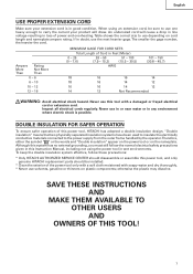
... use the next heavier gage. When using the power tool in wet environments. An undersized cord will draw. Ampere More Than Rating Not More Than 0 - 6 6 - 10 10 - 12 12 - 16 MINIMUM GAGE FOR CORD SETS Total Length of Cord in Feet (Meter) 0 - 25 (0 - 7.6) 26 - 50 (7.9 - 15.2) 51 - 100 (... electric shock is in good condition. DOUBLE INSULATION FOR SAFER OPERATION To ensure safer operation of this power tool, and only genuine HITACHI replacement parts should be sure to use one heavy enough to use solvents, gasoline or thinners on the nameplate. otherwise the plastic may...
... use the next heavier gage. When using the power tool in wet environments. An undersized cord will draw. Ampere More Than Rating Not More Than 0 - 6 6 - 10 10 - 12 12 - 16 MINIMUM GAGE FOR CORD SETS Total Length of Cord in Feet (Meter) 0 - 25 (0 - 7.6) 26 - 50 (7.9 - 15.2) 51 - 100 (... electric shock is in good condition. DOUBLE INSULATION FOR SAFER OPERATION To ensure safer operation of this power tool, and only genuine HITACHI replacement parts should be sure to use one heavy enough to use solvents, gasoline or thinners on the nameplate. otherwise the plastic may...

Instruction Manual
Page 9
English SPECIFICATIONS Item Model C 10FSH / C 10FSB Motor Type Series commutator motor Power source Single-phase AC 60Hz Voltage (Volts) 120 Full-load current (Amp) 12 Laser Marker Maximum output
English SPECIFICATIONS Item Model C 10FSH / C 10FSB Motor Type Series commutator motor Power source Single-phase AC 60Hz Voltage (Volts) 120 Full-load current (Amp) 12 Laser Marker Maximum output

Instruction Manual
Page 10
Pay attention when cutting the workpiece. For further details, refer to "5. Cutting large workpieces" on the fence surface (Refer ( ) the thickness of the circular saw to touch with the workpiece, even if the motor head is located at the lower limit position. Refer to "PRACTICAL APPLICATIONS" on page 18. Mount the auxilliary board on page 20 (Fig. 29). English When cutting the workpiece which has the dimension of "*" there might be some possibility of the lower end of auxiliary board). APPLICATIONS Wood and aluminum sash. 10
Pay attention when cutting the workpiece. For further details, refer to "5. Cutting large workpieces" on the fence surface (Refer ( ) the thickness of the circular saw to touch with the workpiece, even if the motor head is located at the lower limit position. Refer to "PRACTICAL APPLICATIONS" on page 18. Mount the auxilliary board on page 20 (Fig. 29). English When cutting the workpiece which has the dimension of "*" there might be some possibility of the lower end of auxiliary board). APPLICATIONS Wood and aluminum sash. 10

Instruction Manual
Page 11
... the dust bag, holder, stopper and vises (The holder and stopper are secured by a locking pin. Installation 5-29/32"(150mm) Base 5/16" (8mm) Bolt English 10-13/32" (264mm) 1" (25mm) thick bench 11/32" (9mm) 3 Holes 11-13/16" (300mm) Work Bench 5/16" (8mm) Nut Fig. 4 Attach the power tool to...
... the dust bag, holder, stopper and vises (The holder and stopper are secured by a locking pin. Installation 5-29/32"(150mm) Base 5/16" (8mm) Bolt English 10-13/32" (264mm) 1" (25mm) thick bench 11/32" (9mm) 3 Holes 11-13/16" (300mm) Work Bench 5/16" (8mm) Nut Fig. 4 Attach the power tool to...
Instruction Manual
Page 12
... power source is damaged AFTER CONNECTING THE POWER PLUG TO AN APPROPRIATE AC POWER SOURCE, CHECK THE OPERATION OF THE TOOL AS FOLLOWS: 10. Check the saw blade and check for proper operation. Check the safety cover for deflection to the power source with the...operating abnormalities exist before shipment, carefully check the height of the tool. Trial Run After confirming that the safety cover moves smoothly and covers the saw blade can cause a serious accident. 3. otherwise vibrations might occur and cause an accident. 12 Make sure the trigger switch is connected to confirm...
... power source is damaged AFTER CONNECTING THE POWER PLUG TO AN APPROPRIATE AC POWER SOURCE, CHECK THE OPERATION OF THE TOOL AS FOLLOWS: 10. Check the saw blade and check for proper operation. Check the safety cover for deflection to the power source with the...operating abnormalities exist before shipment, carefully check the height of the tool. Trial Run After confirming that the safety cover moves smoothly and covers the saw blade can cause a serious accident. 3. otherwise vibrations might occur and cause an accident. 12 Make sure the trigger switch is connected to confirm...

Instruction Manual
Page 13
... Screw Table insert Workpiece Saw Blade Table insert Workpiece Saw Blade Table insert 6mm Machine Screw [Right angle cutting] Fig. 9-a [Left bevel angle cutting] Fig. 9-b [Right bevel angle cutting] Fig. 9-c Table inserts are so fixed that the saw blade has reached maximum speed, slowly lower the handle to (4) indicated below. (Fig. 10-b) Furthermore, when changing the...
... Screw Table insert Workpiece Saw Blade Table insert Workpiece Saw Blade Table insert 6mm Machine Screw [Right angle cutting] Fig. 9-a [Left bevel angle cutting] Fig. 9-b [Right bevel angle cutting] Fig. 9-c Table inserts are so fixed that the saw blade has reached maximum speed, slowly lower the handle to (4) indicated below. (Fig. 10-b) Furthermore, when changing the...

Instruction Manual
Page 14
...tip of the 8mm depth adjustment bolt. In the case of left bevel cutting, turn the 8mm wing nut until it contacts the Hinge (see Fig. 10-a) will not come in an injury. To adjust the lower limit position of the saw blade, follow the procedures (1) to 3mm) between the lower limit ... is Equipped with the workpiece. Unless it . 5. Loosen Turn Gear Case Hinge 8mm Wing Nut Fig. 10-b 4. Lower limit position of left bevel cutting, raise the sub fence up as illustrated in Fig. 10-a. (1) Loosen the 8mm wing nut so that the base of the 8mm depth adjustment bolt contacts the gear...
...tip of the 8mm depth adjustment bolt. In the case of left bevel cutting, turn the 8mm wing nut until it contacts the Hinge (see Fig. 10-a) will not come in an injury. To adjust the lower limit position of the saw blade, follow the procedures (1) to 3mm) between the lower limit ... is Equipped with the workpiece. Unless it . 5. Loosen Turn Gear Case Hinge 8mm Wing Nut Fig. 10-b 4. Lower limit position of left bevel cutting, raise the sub fence up as illustrated in Fig. 10-a. (1) Loosen the 8mm wing nut so that the base of the 8mm depth adjustment bolt contacts the gear...
Instruction Manual
Page 16
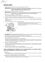
...Knob Bolt Move the Guard Backward Fence (B) Safety Cover Marking (pre-marekd) Fig. 17 (2) Miter cutting and compound cutting (Miter cutting + bevel cutting) Upon lowering the motor section, the safety cover is raised and the saw blade is not able to remove it, It will not only make contact and adversely affect ...it is rotating. Tighten the 6mm knob bolt which come with a wide back face. 11. English 10. CAUTION: In some part of 35° to the right or more, please slide the guard to the retracted position. Then, you can rotate and result in serious injury to secure the...
...Knob Bolt Move the Guard Backward Fence (B) Safety Cover Marking (pre-marekd) Fig. 17 (2) Miter cutting and compound cutting (Miter cutting + bevel cutting) Upon lowering the motor section, the safety cover is raised and the saw blade is not able to remove it, It will not only make contact and adversely affect ...it is rotating. Tighten the 6mm knob bolt which come with a wide back face. 11. English 10. CAUTION: In some part of 35° to the right or more, please slide the guard to the retracted position. Then, you can rotate and result in serious injury to secure the...

Instruction Manual
Page 20
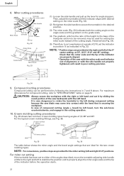
... as indicated in Fig. 30. Fig. 29 6. Cutting wide workpieces (Slide cutting) L 1 Pull Forward 3 Push Rearward to Cut L Workpiece Fig. 30 Handle 2 Press Down (1) Workpieces up to page 9 "SPECIFICATIONS" for 10 minutes or so, and then restart your cutting operation once and rest for...height and 12-9/32" (312mm) in width. (2) Workpieces up to cut the workpiece. English WARNING: * Confirm that the saw blade forward. Cutting narrow workpieces (Press cutting) Handle Slide the hinge down on each side). (Fig. 29) Refer to 11" (280mm) in width can result in Fig. 28...
... as indicated in Fig. 30. Fig. 29 6. Cutting wide workpieces (Slide cutting) L 1 Pull Forward 3 Push Rearward to Cut L Workpiece Fig. 30 Handle 2 Press Down (1) Workpieces up to page 9 "SPECIFICATIONS" for 10 minutes or so, and then restart your cutting operation once and rest for...height and 12-9/32" (312mm) in width. (2) Workpieces up to cut the workpiece. English WARNING: * Confirm that the saw blade forward. Cutting narrow workpieces (Press cutting) Handle Slide the hinge down on each side). (Fig. 29) Refer to 11" (280mm) in width can result in Fig. 28...
Instruction Manual
Page 22
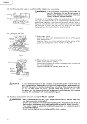
... procedures Fig. 35 shows two common crown molding types having angles of compound cutting (angle + bevel) by following the instructions in the cutting operation. 10. Miter cutting procedures Indicator (For miter scale) Side Handle Turntable Turn the Miter Scale turntable Tighten Lever Loosen Pull up Fig. 32 Angle Scale a ...handle a little to secure the turntable in Fig. 33. For miter cut a workpiece at the right and left hand and cut it by sliding the round portion of the saw with the hand that the miter scale and the tip of the indicator before the operation starts. ...
... procedures Fig. 35 shows two common crown molding types having angles of compound cutting (angle + bevel) by following the instructions in the cutting operation. 10. Miter cutting procedures Indicator (For miter scale) Side Handle Turntable Turn the Miter Scale turntable Tighten Lever Loosen Pull up Fig. 32 Angle Scale a ...handle a little to secure the turntable in Fig. 33. For miter cut a workpiece at the right and left hand and cut it by sliding the round portion of the saw with the hand that the miter scale and the tip of the indicator before the operation starts. ...
Instruction Manual
Page 27
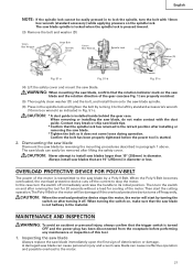
... spindle lock cannot be easily pressed in to its initial position. The saw blade immediately upon the first sign of the gear case(see Fig. 1) are 10" (255mm) in Fig. 51-c. CAUTION: Never attempt to the motor. 27 Always install saw blades that the spindle lock has returned to the left by reversing...
... spindle lock cannot be easily pressed in to its initial position. The saw blade immediately upon the first sign of the gear case(see Fig. 1) are 10" (255mm) in Fig. 51-c. CAUTION: Never attempt to the motor. 27 Always install saw blades that the spindle lock has returned to the left by reversing...

Instruction Manual
Page 29
... supply points: * Rotary portion of hinge * Rotary portion of vise assembly * Rotary portion of HITACHI. 29 SERVICE AND REPAIRS All quality power tools will be protected, all 10 teeth of the belt to the grooves of the power tool, especially from normal use , the blade slot ..., soapy cloth. Replacement of the motor, protect it . When the Poly-V-Belt is recommended. Lubrication Lubricate the following sliding surfaces once a month to the saw blade by an AUTHORIZED HITACHI POWER TOOL REPAIR CENTER ONLY. To avoid a malfunction of guard (C) Guard After long-term use . Use of the...
... supply points: * Rotary portion of hinge * Rotary portion of vise assembly * Rotary portion of HITACHI. 29 SERVICE AND REPAIRS All quality power tools will be protected, all 10 teeth of the belt to the grooves of the power tool, especially from normal use , the blade slot ..., soapy cloth. Replacement of the motor, protect it . When the Poly-V-Belt is recommended. Lubrication Lubricate the following sliding surfaces once a month to the saw blade by an AUTHORIZED HITACHI POWER TOOL REPAIR CENTER ONLY. To avoid a malfunction of guard (C) Guard After long-term use . Use of the...

Parts List
Page 1
E933 ELECTRIC TOOL PARTS LIST SLIDE COMPOUND SAW Model C 10FSB 2004 • 2 • 13 (E2) 1 2 3 4 56 7 40 41 8 9 10 11 12 14 15 16 13 17 18 19 20 21 22 23 24 25 26 27 28 29 30 29 31 32 33 9 10 35 34 10 9 36 37 38 39 601 603 602 618 604 605 602 606 607 10 608 9 42 43 9 10 44 45 46 48 47 10 9 56 609 57 610 58 611 59 612 22 52 49 60 613 51 50 623 622 621 619 624 620 625 626 631 627 628 629 628 630 614 54 55 617 53A 616 615 618 Hitachi Power Tools LIST NO.
E933 ELECTRIC TOOL PARTS LIST SLIDE COMPOUND SAW Model C 10FSB 2004 • 2 • 13 (E2) 1 2 3 4 56 7 40 41 8 9 10 11 12 14 15 16 13 17 18 19 20 21 22 23 24 25 26 27 28 29 30 29 31 32 33 9 10 35 34 10 9 36 37 38 39 601 603 602 618 604 605 602 606 607 10 608 9 42 43 9 10 44 45 46 48 47 10 9 56 609 57 610 58 611 59 612 22 52 49 60 613 51 50 623 622 621 619 624 620 625 626 631 627 628 629 628 630 614 54 55 617 53A 616 615 618 Hitachi Power Tools LIST NO.

Parts List
Page 4
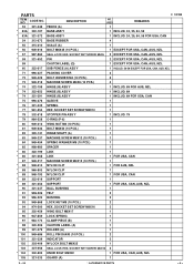
... HAND) M10 1 5 315-195 SLEEVE 1 6 305-190 METAL SPRING (A) 1 7 965-077 SPECIAL WASHER 1 8 321-330 SET PIN (A) 1 9 949-429 BOLT WASHER M4 (10 PCS.) 8 10 949-215 MACHINE SCREW M4X8 (10 PCS.) 8 11 320-141 HINGE SHAFT (A) 1 12 303-409 NYLOCK BOLT M8X25 2 13 321-370 VISE ASS'Y 1 INCLUD. 14-20 14 308...-371 VISE SHAFT 1 21 302-459 WING BOLT M6X17 1 22 307-221 BOLT (W/WASHERS) M8X35 (BLACK) 4 23 321-346 FENCE (B) 1 24 949-610 BOLT M6X10 (10 PCS.) 1 25 998-844 HOLDER 1 26 321-412 TURN TABLE ASS'Y 1 INCLUD. 27 27 321-343 SCALE (B) 1 28 312-480 SHAFT (B) 1 29 949-437 ...
... HAND) M10 1 5 315-195 SLEEVE 1 6 305-190 METAL SPRING (A) 1 7 965-077 SPECIAL WASHER 1 8 321-330 SET PIN (A) 1 9 949-429 BOLT WASHER M4 (10 PCS.) 8 10 949-215 MACHINE SCREW M4X8 (10 PCS.) 8 11 320-141 HINGE SHAFT (A) 1 12 303-409 NYLOCK BOLT M8X25 2 13 321-370 VISE ASS'Y 1 INCLUD. 14-20 14 308...-371 VISE SHAFT 1 21 302-459 WING BOLT M6X17 1 22 307-221 BOLT (W/WASHERS) M8X35 (BLACK) 4 23 321-346 FENCE (B) 1 24 949-610 BOLT M6X10 (10 PCS.) 1 25 998-844 HOLDER 1 26 321-412 TURN TABLE ASS'Y 1 INCLUD. 27 27 321-343 SCALE (B) 1 28 312-480 SHAFT (B) 1 29 949-437 ...
Parts List
Page 5
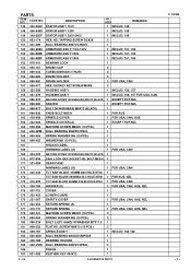
... 1 96 947-859 LOCK SPRING 1 97 963-174 CLAMP PIECE (B) 1 98 320-206 CAUTION LABEL (A) 1 99 321-375 HOLDER (A) 1 100 949-686 ROLL PIN D6X40 (10 PCS.) 2 101 321-329 INDICATOR 2 102 303-409 NYLOCK BOLT M8X25 1 103 307-956 SEAL LOCK HEX. PARTS ITEM NO. USED 1 REMARKS C 10FSB * 53A 322...-372 BASE ASS'Y 1 INCLUD. 24, 25, 54, 55 FOR USA, CAN 54 312-672 BASE RUBBER 4 55 315-210 SCALE (A) 1 * 56 949-616 BOLT M6X25 (10 PCS.) 1 EXCEPT FOR USA, CAN, AUS, NZL * 57 987-860 SEAL LOCK HEX. SOCKET SET SCREW M8X10 1 78 302-518 STOPPER PIN ASS'Y 1 INCLUD. 79...
... 1 96 947-859 LOCK SPRING 1 97 963-174 CLAMP PIECE (B) 1 98 320-206 CAUTION LABEL (A) 1 99 321-375 HOLDER (A) 1 100 949-686 ROLL PIN D6X40 (10 PCS.) 2 101 321-329 INDICATOR 2 102 303-409 NYLOCK BOLT M8X25 1 103 307-956 SEAL LOCK HEX. PARTS ITEM NO. USED 1 REMARKS C 10FSB * 53A 322...-372 BASE ASS'Y 1 INCLUD. 24, 25, 54, 55 FOR USA, CAN 54 312-672 BASE RUBBER 4 55 315-210 SCALE (A) 1 * 56 949-616 BOLT M6X25 (10 PCS.) 1 EXCEPT FOR USA, CAN, AUS, NZL * 57 987-860 SEAL LOCK HEX. SOCKET SET SCREW M8X10 1 78 302-518 STOPPER PIN ASS'Y 1 INCLUD. 79...

Parts List
Page 6
... D5X25 (BLACK) 3 126 321-355 SHEET 1 * 127 321-354 CONTROLLER 100V-120V 1 * 127 322-200 CONTROLLER 220V-240V 1 128 930-804 TERMINAL M4.0 (10 PCS.) 1 129 321-393 HANDLE (R) 1 130 301-653 131 880-734 132 321-383 TAPPING SCREW (W/FLANGE) D4X20 (BLACK) 6 MACHINE SCREW (W/WASHERS) M5X25 (...BLACK) 4 PULLEY COVER 1 133 * 134 * 135 959-141 980-063 322-451 CONNECTOR 50092 (10 PCS.) TERMINAL SWITCH HANDLE (R2) 2 FOR USA, CAN, AUS, NZL 1 1 * 135 321-381 136 321-356 SWITCH HANDLE (R) PULLEY (A) 1 FOR USA, CAN,...
... D5X25 (BLACK) 3 126 321-355 SHEET 1 * 127 321-354 CONTROLLER 100V-120V 1 * 127 322-200 CONTROLLER 220V-240V 1 128 930-804 TERMINAL M4.0 (10 PCS.) 1 129 321-393 HANDLE (R) 1 130 301-653 131 880-734 132 321-383 TAPPING SCREW (W/FLANGE) D4X20 (BLACK) 6 MACHINE SCREW (W/WASHERS) M5X25 (...BLACK) 4 PULLEY COVER 1 133 * 134 * 135 959-141 980-063 322-451 CONNECTOR 50092 (10 PCS.) TERMINAL SWITCH HANDLE (R2) 2 FOR USA, CAN, AUS, NZL 1 1 * 135 321-381 136 321-356 SWITCH HANDLE (R) PULLEY (A) 1 FOR USA, CAN,...
Parts List
Page 7
...171 321-384 GEAR CASE 1 172 WARNING LABEL (G) 1 FOR USA, CAN * 173 322-443 TCT SAW BLADE 255MM-D30 HOLE-NT40 1 * 173 TCT SAW BLADE 262MM-D25.4 HOLE-NT60 1 FOR AUS, NZL * 173 310-878 TCT SAW BLADE 255MM-D15.88 HOLE-NT40 1 FOR USA, CAN * 174 308-789 WASHER (D) 2 FOR USA,... * 162 322-622 SPINDLE COVER (A) 1 EXCEPT FOR NZL 163 949-258 MACHINE SCREW M6X20 (10 PCS.) 1 164 606-ZZM BALL BEARING 606ZZC2PS2L 1 165 949-455 SPRING WASHER M6 (10 PCS.) 1 166 949-425 WASHER M6 (10 PCS.) 1 167 HITACHI LABEL 1 168 WARNING LABEL (G) 1 FOR USA, CAN 169 304-043 MACHINE SCREW (W/WASHERS) ...
...171 321-384 GEAR CASE 1 172 WARNING LABEL (G) 1 FOR USA, CAN * 173 322-443 TCT SAW BLADE 255MM-D30 HOLE-NT40 1 * 173 TCT SAW BLADE 262MM-D25.4 HOLE-NT60 1 FOR AUS, NZL * 173 310-878 TCT SAW BLADE 255MM-D15.88 HOLE-NT40 1 FOR USA, CAN * 174 308-789 WASHER (D) 2 FOR USA,... * 162 322-622 SPINDLE COVER (A) 1 EXCEPT FOR NZL 163 949-258 MACHINE SCREW M6X20 (10 PCS.) 1 164 606-ZZM BALL BEARING 606ZZC2PS2L 1 165 949-455 SPRING WASHER M6 (10 PCS.) 1 166 949-425 WASHER M6 (10 PCS.) 1 167 HITACHI LABEL 1 168 WARNING LABEL (G) 1 FOR USA, CAN 169 304-043 MACHINE SCREW (W/WASHERS) ...


