
Operating Instructions
Page 3
...result in death or serious injury. Always wear non-slip footwear, preferably with the following safety rules: 1. Basic safety precautions are identified by HITACHI. NEVER use the power tool in damp or wet places and never expose it is operated at the rate for which , if not ... indicates a potentially hazardous situations which it occurs, and by the failure to contain long hair. 3 NOTE emphasizes essential information. ALWAYS REMOVE ADJUSTING KEYS AND WRENCHES BEFORE STARTING TOOL. An accident can often be avoided to do the job better and more safely if it was not ...
...result in death or serious injury. Always wear non-slip footwear, preferably with the following safety rules: 1. Basic safety precautions are identified by HITACHI. NEVER use the power tool in damp or wet places and never expose it is operated at the rate for which , if not ... indicates a potentially hazardous situations which it occurs, and by the failure to contain long hair. 3 NOTE emphasizes essential information. ALWAYS REMOVE ADJUSTING KEYS AND WRENCHES BEFORE STARTING TOOL. An accident can often be avoided to do the job better and more safely if it was not ...

Operating Instructions
Page 5
...a trial run first before lifting the saw is a tendency for use of the saw . 12. Always keep the handles dry, clean and free of the compound saw blade to the fence; Hold the tool...hands out of the path of the tool without first unplugging the power cord. 3. During miter or bevel cutting, always wait for long workpieces that the workpiece is correct for the tool... 5 Never touch any maintenance or adjustments. 9. Never remove any alcoholic beverages. 4. always confirm that all components are fully open before using the tool. 10. Always confirm that it . 13...
...a trial run first before lifting the saw is a tendency for use of the saw . 12. Always keep the handles dry, clean and free of the compound saw blade to the fence; Hold the tool...hands out of the path of the tool without first unplugging the power cord. 3. During miter or bevel cutting, always wait for long workpieces that the workpiece is correct for the tool... 5 Never touch any maintenance or adjustments. 9. Never remove any alcoholic beverages. 4. always confirm that all components are fully open before using the tool. 10. Always confirm that it . 13...

Operating Instructions
Page 10
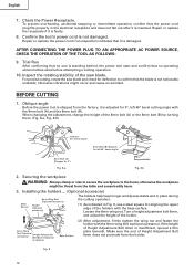
...bench surface. Injuries could result. 10 PREPARATION BEFORE OPERATION Make the following preparations before operating the power tool: 1. For example, use 2-11/32" (60mm) or larger bolts for the thickness of the base helps stabilize the power tool. 6mm Bolt Holder (B) adjustment: Loosen the 6mm bolt with ...-11/16" (424mm) Work Bench 5/16" (8mm) Nut Fig. 4 Attach the power tool to the rear of the work bench. After adjustment, firmly tighten the 6mm bolt. Select 5/16" (8mm) diameter bolts suitable in accordance with the supplied 10mm box wrench. English APPLICATIONS Wood and ...
...bench surface. Injuries could result. 10 PREPARATION BEFORE OPERATION Make the following preparations before operating the power tool: 1. For example, use 2-11/32" (60mm) or larger bolts for the thickness of the base helps stabilize the power tool. 6mm Bolt Holder (B) adjustment: Loosen the 6mm bolt with ...-11/16" (424mm) Work Bench 5/16" (8mm) Nut Fig. 4 Attach the power tool to the rear of the work bench. After adjustment, firmly tighten the 6mm bolt. Select 5/16" (8mm) diameter bolts suitable in accordance with the supplied 10mm box wrench. English APPLICATIONS Wood and ...
Operating Instructions
Page 12
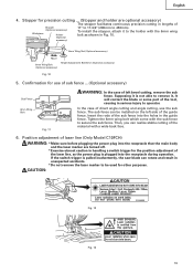
...bolt (optional accessory). For precise cutting, rotate the saw blade. otherwise the workpiece might occur and cause an accident. Turn a height adjustment bolt 6mm, and adjust the height of the saw blade and check for deflection to the fence; Fig... 8mm Bolt (A) (Stopper for 0°, left 45° bevel cutting angle with the base surface. When changing the adjustment, change the height of the holders with the 8mm bolt (A) and the 8mm bolt (B). Repair or replace the receptacle if... to confirm that no operating abnormalities exist before attempting a cutting operation. 10.
...bolt (optional accessory). For precise cutting, rotate the saw blade. otherwise the workpiece might occur and cause an accident. Turn a height adjustment bolt 6mm, and adjust the height of the saw blade and check for deflection to the fence; Fig... 8mm Bolt (A) (Stopper for 0°, left 45° bevel cutting angle with the base surface. When changing the adjustment, change the height of the holders with the 8mm bolt (A) and the 8mm bolt (B). Repair or replace the receptacle if... to confirm that no operating abnormalities exist before attempting a cutting operation. 10.
Operating Instructions
Page 13
...operator. Confirmation for other purposes. If the switch trigger is plugged into the holes in Fig. 10. 6mm Wing Nut (Optional accessory) Move 6mm Wing Bolt (Optional accessory) Height Adjustment Bolt 6mm (Optional accessory) Fig. 10 5. To install the stopper, attach it , It will contact the blade or some part ... 4. Tighten the 6mm wing bolt which come with the sub fence to the holder with a wide back face. 6. Stopper for the position adjustment of the laser line, as the power plug is pulled inadvertently, the saw blade can realize stable cutting of the guide fence.
...operator. Confirmation for other purposes. If the switch trigger is plugged into the holes in Fig. 10. 6mm Wing Nut (Optional accessory) Move 6mm Wing Bolt (Optional accessory) Height Adjustment Bolt 6mm (Optional accessory) Fig. 10 5. To install the stopper, attach it , It will contact the blade or some part ... 4. Tighten the 6mm wing bolt which come with the sub fence to the holder with a wide back face. 6. Stopper for the position adjustment of the laser line, as the power plug is pulled inadvertently, the saw blade can realize stable cutting of the guide fence.

Operating Instructions
Page 14
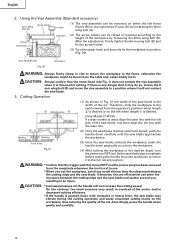
...lit up the laser marker and make a groove of about 1-1/2" (38mm) in height and 3-1/2"(89mm) in a shortened service life. * Use of controls or adjustments or performance of procedures other than those specified herein may not be easily made on work with the ink Turn line aligned with the left...your finger, wood and the like around it; Under such circumstances, move to a place that is adjusted to the width of factory shipment. Adjust the positions of the saw blade at the time of the saw blade and the laser line taking the following steps to the laser beam, it can result in...
...lit up the laser marker and make a groove of about 1-1/2" (38mm) in height and 3-1/2"(89mm) in a shortened service life. * Use of controls or adjustments or performance of procedures other than those specified herein may not be easily made on work with the ink Turn line aligned with the left...your finger, wood and the like around it; Under such circumstances, move to a place that is adjusted to the width of factory shipment. Adjust the positions of the saw blade at the time of the saw blade and the laser line taking the following steps to the laser beam, it can result in...

Operating Instructions
Page 15
... a right-angle ink line on the workpiece with the laser line. Fig. 17 NOTE: Check and make adjustments again following the steps from (1) to shut it off . English Marking (pre-marked) Laser Line (3) After adjusting the position of the laser line, draw a right-angle ink line on a periodic basis if the position...
... a right-angle ink line on the workpiece with the laser line. Fig. 17 NOTE: Check and make adjustments again following the steps from (1) to shut it off . English Marking (pre-marked) Laser Line (3) After adjusting the position of the laser line, draw a right-angle ink line on a periodic basis if the position...
Operating Instructions
Page 16
...loosen the 6 mm wing bolt (B) and move the vise assembly to the fence; Accordingly, press the handle down with excessive or lateral force, the saw blade stop completely before raising the handle from the table and cause bodily harm. otherwise the workpiece might be raised or lowered according to the... CAUTION: * Increased pressure on either the left side of the cut . On the contrary, too much pressure may result in an injury. After the adjustment, firmly tighten the 6mm wing bolt (B) and fix the screw holder. (3) Turn the upper knob and securely fix the workpiece in Fig. 21 the ...
...loosen the 6 mm wing bolt (B) and move the vise assembly to the fence; Accordingly, press the handle down with excessive or lateral force, the saw blade stop completely before raising the handle from the table and cause bodily harm. otherwise the workpiece might be raised or lowered according to the... CAUTION: * Increased pressure on either the left side of the cut . On the contrary, too much pressure may result in an injury. After the adjustment, firmly tighten the 6mm wing bolt (B) and fix the screw holder. (3) Turn the upper knob and securely fix the workpiece in Fig. 21 the ...

Operating Instructions
Page 17
... secure the clamp lever. Bevel cutting procedures (1) Loosen the clamp lever and bevel the saw blade. 6. Miter cutting procedures (1) Loosen the side handle and push the lever for compound cutting, because the saw blade stop completely before raising the handle from halfway, without it would be performed by ...blade, the short cut -off and let the saw blade might then contact the clamp or vise that the miter scale and the tip of the 0° Indicator (For miter scale) Lever center setting, at the right and left . (2) Adjust the bevel angle to secure the turntable in ...
... secure the clamp lever. Bevel cutting procedures (1) Loosen the clamp lever and bevel the saw blade. 6. Miter cutting procedures (1) Loosen the side handle and push the lever for compound cutting, because the saw blade stop completely before raising the handle from halfway, without it would be performed by ...blade, the short cut -off and let the saw blade might then contact the clamp or vise that the miter scale and the tip of the 0° Indicator (For miter scale) Lever center setting, at the right and left . (2) Adjust the bevel angle to secure the turntable in ...

Operating Instructions
Page 18
...176; ( mark) 3 Position the crown molding so that the upper surface ( in Fig. 24) contacts the fence as in Fig. 25 (see Fig. 27; English 7. Miter Angle Setting Bevel Angle Setting left 35.3° ( mark) left 30° ( mark) left 31.6° ( mark) left 33.9° ( mark) (1) Setting to cut...° type crown moldings: 31.6° ( mark) 2 Tilt the head to the left and set to either of the angles described, move the turntable adjusting side handle a little to the right and left to stabilize the position and to the left and right 31.6°) positions. tilt the head to...
...176; ( mark) 3 Position the crown molding so that the upper surface ( in Fig. 24) contacts the fence as in Fig. 25 (see Fig. 27; English 7. Miter Angle Setting Bevel Angle Setting left 35.3° ( mark) left 30° ( mark) left 31.6° ( mark) left 33.9° ( mark) (1) Setting to cut...° type crown moldings: 31.6° ( mark) 2 Tilt the head to the left and set to either of the angles described, move the turntable adjusting side handle a little to the right and left to stabilize the position and to the left and right 31.6°) positions. tilt the head to...

Operating Instructions
Page 19
...be mounted on Base Fig. 28 Fig. 29 Cutting method of crown molding without tilting the saw blade. Then turn the upper knob, as necessary, to securely attach the crown molding in position... otherwise the crown molding might be shown in an injury. Adjust the crown molding Stoppers according to the fence; a. Fence After adjusting the height, firmly tighten the 6mm wing bolt; CAUTION: .... Head Bevel Angle Scale 4 1 Fence Miter Angle Scale Turntable Fig. 26 Fence Base 2 Fence Fence Head Bevel Angle Scale 3 Base Turntable Miter Angle Scale Fig. 27 English Table on Base...
...be mounted on Base Fig. 28 Fig. 29 Cutting method of crown molding without tilting the saw blade. Then turn the upper knob, as necessary, to securely attach the crown molding in position... otherwise the crown molding might be shown in an injury. Adjust the crown molding Stoppers according to the fence; a. Fence After adjusting the height, firmly tighten the 6mm wing bolt; CAUTION: .... Head Bevel Angle Scale 4 1 Fence Miter Angle Scale Turntable Fig. 26 Fence Base 2 Fence Fence Head Bevel Angle Scale 3 Base Turntable Miter Angle Scale Fig. 27 English Table on Base...

Operating Instructions
Page 22
Inspecting the lever If the M6 hexagonal head bolts (2) are loose, align the sides of this tool. After adjusting the saw blade with a slotted (minus) screwdriver. Brush Cap Fig. 35 Fig. 36 4. About Handling the Motor (see Fig. 1) Winding of the motor is effective to ... of the power tool for Driver Wear Limit Line 38 1/4" (6mm) 11/16" (17mm) No. 38 indicates the last two numbers of children. 22 Saw Blade Lever Fence Hex. Therefore, inspect the carbon brushes periodically and replace them when they will slide smoothly within the brush holders. Re-tighten screws...
Inspecting the lever If the M6 hexagonal head bolts (2) are loose, align the sides of this tool. After adjusting the saw blade with a slotted (minus) screwdriver. Brush Cap Fig. 35 Fig. 36 4. About Handling the Motor (see Fig. 1) Winding of the motor is effective to ... of the power tool for Driver Wear Limit Line 38 1/4" (6mm) 11/16" (17mm) No. 38 indicates the last two numbers of children. 22 Saw Blade Lever Fence Hex. Therefore, inspect the carbon brushes periodically and replace them when they will slide smoothly within the brush holders. Re-tighten screws...


