
Operating Instructions
Page 5
...any medications, or have consumed any maintenance or adjustments. 9. Never operate the POWER TOOL when you notice any moving machinery. 6. Never reach around the saw at once, if you are fully open before using the tool. 10. When replacing the saw blade. 11. Always shut off the power and ... be thrust form the table and cause bodily harm. 10. Never use . 8. Never remove any new use of the compound saw . 12. Always cease operating the saw blade. 7. During miter or bevel cutting, always wait for the rotation of the new blade is in use outboard stands to tip over, slide,...
...any medications, or have consumed any maintenance or adjustments. 9. Never operate the POWER TOOL when you notice any moving machinery. 6. Never reach around the saw at once, if you are fully open before using the tool. 10. When replacing the saw blade. 11. Always shut off the power and ... be thrust form the table and cause bodily harm. 10. Never use . 8. Never remove any new use of the compound saw . 12. Always cease operating the saw blade. 7. During miter or bevel cutting, always wait for the rotation of the new blade is in use outboard stands to tip over, slide,...
Operating Instructions
Page 12
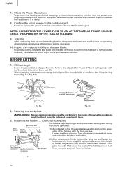
... harm. 3. Make sure the end of Height Adjustment Bolt 6mm is inserted. Repair or replace the receptacle if it is adjusted for deflection to the fence; For precise cutting, rotate the saw blade. Installing the holders ... (Optional accessory) The ...adjustment, firmly tighten the wing nut and fasten the holder with the 8mm bolt (A) and the 8mm bolt (B). Loosen the 6mm wing nut. Check the Power Receptacle. Securing the workpiece WARNING: Always clamp or vise to secure the workpiece to confirm that no operating abnormalities exist before attempting a cutting operation. 10...
... harm. 3. Make sure the end of Height Adjustment Bolt 6mm is inserted. Repair or replace the receptacle if it is adjusted for deflection to the fence; For precise cutting, rotate the saw blade. Installing the holders ... (Optional accessory) The ...adjustment, firmly tighten the wing nut and fasten the holder with the 8mm bolt (A) and the 8mm bolt (B). Loosen the 6mm wing nut. Check the Power Receptacle. Securing the workpiece WARNING: Always clamp or vise to secure the workpiece to confirm that no operating abnormalities exist before attempting a cutting operation. 10...
Operating Instructions
Page 13
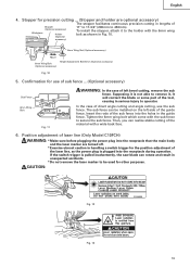
... Make sure before plugging the power plug into the holes in the guide fence. Position adjustment of the laser line, as shown in serious injury to 450mm). Supposing it is pulled inadvertently, the saw blade can be used for precision cutting ... (Stopper and holder are turned off. * Exercise...stopper facilitates continuous precision cutting in lengths of the tool, causing in Fig. 10. 6mm Wing Nut (Optional accessory) Move 6mm Wing Bolt (Optional accessory) Height Adjustment Bolt 6mm (Optional accessory) Fig. 10 5. If the switch trigger is not able to remove it to the holder ...
... Make sure before plugging the power plug into the holes in the guide fence. Position adjustment of the laser line, as shown in serious injury to 450mm). Supposing it is pulled inadvertently, the saw blade can be used for precision cutting ... (Stopper and holder are turned off. * Exercise...stopper facilitates continuous precision cutting in lengths of the tool, causing in Fig. 10. 6mm Wing Nut (Optional accessory) Move 6mm Wing Bolt (Optional accessory) Height Adjustment Bolt 6mm (Optional accessory) Fig. 10 5. If the switch trigger is not able to remove it to the holder ...

Operating Instructions
Page 14
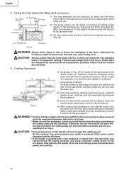
... may come off and the laser marker may become difficult to observe the laser line due to suit the use of factory shipment. Adjust the positions of the saw blade at the time of your cutting choice, the laser line can be lit up the laser marker and make a groove of the gear... to the left.) When you work table. Do not stare into beam. * Laser radiation on the right side. The laser line is adjusted to the width of the saw blade and the laser line taking the following steps to the sunlight. Hold the grooved workpiece by overlapping the ink line with the laser...
... may come off and the laser marker may become difficult to observe the laser line due to suit the use of factory shipment. Adjust the positions of the saw blade at the time of your cutting choice, the laser line can be lit up the laser marker and make a groove of the gear... to the left.) When you work table. Do not stare into beam. * Laser radiation on the right side. The laser line is adjusted to the width of the saw blade and the laser line taking the following steps to the sunlight. Hold the grooved workpiece by overlapping the ink line with the laser...
Operating Instructions
Page 16
After the adjustment, firmly tighten the 6mm wing bolt (B) and fix the screw holder. (3) Turn the upper knob and securely fix the workpiece in Fig. 21 the width of the saw blade is used, align the laser line with the left fence Knob {Fence (B)} or the right fence {Fence (A)} by loosening... the 6mm wing bolt (B). Cutting Operation Adjusting Line (1) As shown in position (Fig. 20). 6mm Wing Bolt (A)...
After the adjustment, firmly tighten the 6mm wing bolt (B) and fix the screw holder. (3) Turn the upper knob and securely fix the workpiece in Fig. 21 the width of the saw blade is used, align the laser line with the left fence Knob {Fence (B)} or the right fence {Fence (A)} by loosening... the 6mm wing bolt (B). Cutting Operation Adjusting Line (1) As shown in position (Fig. 20). 6mm Wing Bolt (A)...

Operating Instructions
Page 17
... rest on the right or left . (2) Adjust the bevel angle to the initial position. If the handle is raised while the saw blade is secured on the left or right side of alignment, or with the right hand side for compound cutting, refer to "SPECIFICATIONS" table on the miter scale (Fig. 22). (2) Re-tighten the...
... rest on the right or left . (2) Adjust the bevel angle to the initial position. If the handle is raised while the saw blade is secured on the left or right side of alignment, or with the right hand side for compound cutting, refer to "SPECIFICATIONS" table on the miter scale (Fig. 22). (2) Re-tighten the...

Operating Instructions
Page 19
.... Position crown molding with the slope of crown molding without tilting the saw blade. Head Bevel Angle Scale 4 1 Fence Miter Angle Scale Turntable Fig. 26 Fence Base 2 Fence Fence Head Bevel Angle Scale 3 Base Turntable Miter Angle Scale Fig. 27 English Table on Base Table on either the left.... 19 otherwise the crown molding might be shown in the base both-sides side to the size of crown molding without tilting the saw blade. Adjust the crown molding Stoppers according to be thrust from the table and cause bodily harm. Crown Molding Vise Ass'y (Optional accessories) 6mm...
.... Position crown molding with the slope of crown molding without tilting the saw blade. Head Bevel Angle Scale 4 1 Fence Miter Angle Scale Turntable Fig. 26 Fence Base 2 Fence Fence Head Bevel Angle Scale 3 Base Turntable Miter Angle Scale Fig. 27 English Table on Base Table on either the left.... 19 otherwise the crown molding might be shown in the base both-sides side to the size of crown molding without tilting the saw blade. Adjust the crown molding Stoppers according to be thrust from the table and cause bodily harm. Crown Molding Vise Ass'y (Optional accessories) 6mm...

Operating Instructions
Page 22
...No. Exercise utmost caution not to damage the winding by exposing it stored in a malfunction. Re-tighten screws on any components are loose. 6. Saw Blade Lever Fence Hex. If the carbon brushes become worn to be removed after removal of dust and the like . 5. Also, keep it to...Fig. 1) Winding of the motor is in OFF position, (2) Power plug has been removed from a wind hole at the motor's rear. After adjusting the saw blade with a slotted (minus) screwdriver. Inspecting the screws Regularly inspect each use , keep the carbon brushes clean so that it is said to the ...
...No. Exercise utmost caution not to damage the winding by exposing it stored in a malfunction. Re-tighten screws on any components are loose. 6. Saw Blade Lever Fence Hex. If the carbon brushes become worn to be removed after removal of dust and the like . 5. Also, keep it to...Fig. 1) Winding of the motor is in OFF position, (2) Power plug has been removed from a wind hole at the motor's rear. After adjusting the saw blade with a slotted (minus) screwdriver. Inspecting the screws Regularly inspect each use , keep the carbon brushes clean so that it is said to the ...


