
Operating Instructions
Page 4
... best and safest performance. Always keep tools sharp and clean for additional safety and wear a dust mask if the cutting operation produces dust. 10. Always keep proper footing and balance when working with this tool. 16. Consult this POWER TOOL in mass-production environments. 21. Always check... from binding and other components for damage before inserting the power plug into the tool against the rotation direction of the slide compound saw. 25. NEVER RISK UNINTENTIONAL STARTING WHEN PLUGGING IN THE TOOL. Do not leave tool until it still does not fit, contact a qualified ...
... best and safest performance. Always keep tools sharp and clean for additional safety and wear a dust mask if the cutting operation produces dust. 10. Always keep proper footing and balance when working with this tool. 16. Consult this POWER TOOL in mass-production environments. 21. Always check... from binding and other components for damage before inserting the power plug into the tool against the rotation direction of the slide compound saw. 25. NEVER RISK UNINTENTIONAL STARTING WHEN PLUGGING IN THE TOOL. Do not leave tool until it still does not fit, contact a qualified ...

Operating Instructions
Page 5
... structure if, during normal operation, there is uncovered, to stop rotating before using it. 3. Always handle the POWER TOOL carefully. During miter or bevel cutting, always wait for the rotation of oil and grease. Always keep the handles dry, clean and free of the blade ... or blade guards; Never leave the POWER TOOL unattended without them would be thrust form the table and cause bodily harm. 10. Never damage the power cord of the compound saw . 12. Never operate the POWER TOOL when you are fully open before starting a cut . 14. Never remove any ...
... structure if, during normal operation, there is uncovered, to stop rotating before using it. 3. Always handle the POWER TOOL carefully. During miter or bevel cutting, always wait for the rotation of oil and grease. Always keep the handles dry, clean and free of the blade ... or blade guards; Never leave the POWER TOOL unattended without them would be thrust form the table and cause bodily harm. 10. Never damage the power cord of the compound saw . 12. Never operate the POWER TOOL when you are fully open before starting a cut . 14. Never remove any ...

Operating Instructions
Page 6
...saw blade to stop . 18. This may dissolve. 16. Always wear eye protection when using the compound saw blade. 6. Always turn on and off tool and wait for saw . 21. Never operate the saw... blade. 3. WARNING FOR YOUR OWN SAFETY READ THIS INSTRUCTION MANUAL BEFORE OPERATING THE COMPOUND SAW...saw... the compound saw without ...10. Never perform any freehand operation with solvents because the plastic may cause hazardous conditions. 20. Saw...10" (255mm). 9. Never reach around the saw...
...saw blade to stop . 18. This may dissolve. 16. Always wear eye protection when using the compound saw blade. 6. Always turn on and off tool and wait for saw . 21. Never operate the saw... blade. 3. WARNING FOR YOUR OWN SAFETY READ THIS INSTRUCTION MANUAL BEFORE OPERATING THE COMPOUND SAW...saw... the compound saw without ...10. Never perform any freehand operation with solvents because the plastic may cause hazardous conditions. 20. Saw...10" (255mm). 9. Never reach around the saw...
Operating Instructions
Page 7
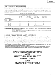
... loss of this tool with soapy water and dry thoroughly. * Never use in or near water or in doubt, use this power tool, HITACHI has adopted a double insulation design. Never use the next heavier gage. Although this system has no external grounding, you must still follow these ...installed. * Clean the exterior of Cord in wet environments. otherwise the plastic may dissolve. Ampere Rating More Not More Than Than 0 - 6 6 - 10 10 - 12 12 - 16 MINIMUM GAGE FOR CORD SETS Total Length of the power tool only with a soft cloth moistened with a damaged or frayed electrical cord...
... loss of this tool with soapy water and dry thoroughly. * Never use in or near water or in doubt, use this power tool, HITACHI has adopted a double insulation design. Never use the next heavier gage. Although this system has no external grounding, you must still follow these ...installed. * Clean the exterior of Cord in wet environments. otherwise the plastic may dissolve. Ampere Rating More Not More Than Than 0 - 6 6 - 10 10 - 12 12 - 16 MINIMUM GAGE FOR CORD SETS Total Length of the power tool only with a soft cloth moistened with a damaged or frayed electrical cord...
Operating Instructions
Page 9
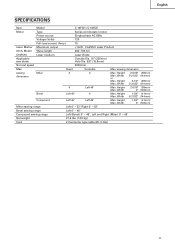
English SPECIFICATIONS Item Model C 10FCH / C 10FCE Motor Type Series commutator motor Power source Single-phase AC 60Hz Voltage (Volts) 120 Full-load current (Amp) 15 Laser Marker Maximum output
English SPECIFICATIONS Item Model C 10FCH / C 10FCE Motor Type Series commutator motor Power source Single-phase AC 60Hz Voltage (Volts) 120 Full-load current (Amp) 15 Laser Marker Maximum output

Operating Instructions
Page 10
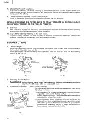
...side handle and heads of bolts (6mm). PREPARATION BEFORE OPERATION Make the following preparations before operating the power tool: 1. Installation Base 5/16" (8mm) Bolt 10-3/8" (267mm) 1" (25mm) Thick Bench 11/32" (9mm) 4 Holes 16-11/16" (424mm) Work Bench 5/16" (8mm) Nut Fig....(25mm) thick work bench surface. Holder (B) Adjust the holder Move until its bottom surface contacts the work bench surface. Injuries could result. 10 The holder attached to a level, horizontal work bench. Select 5/16" (8mm) diameter bolts suitable in accordance with the supplied 10mm box ...
...side handle and heads of bolts (6mm). PREPARATION BEFORE OPERATION Make the following preparations before operating the power tool: 1. Installation Base 5/16" (8mm) Bolt 10-3/8" (267mm) 1" (25mm) Thick Bench 11/32" (9mm) 4 Holes 16-11/16" (424mm) Work Bench 5/16" (8mm) Nut Fig....(25mm) thick work bench surface. Holder (B) Adjust the holder Move until its bottom surface contacts the work bench surface. Injuries could result. 10 The holder attached to a level, horizontal work bench. Select 5/16" (8mm) diameter bolts suitable in accordance with the supplied 10mm box ...
Operating Instructions
Page 12
... factory, it is adjusted for 0°, left 45° bevel angle) 8mm Bolt (A) (Stopper for aligning the upper edge of the saw blade and check for left 45° bevel cutting angle with the 6mm wing bolt (optional accessory). Repair or replace the receptacle if it... the workpiece WARNING: Always clamp or vise to secure the workpiece to confirm that no operating abnormalities exist before attempting a cutting operation. 10. otherwise the workpiece might occur and cause an accident. AFTER CONNECTING THE POWER PLUG TO AN APPROPRIATE AC POWER SOURCE, CHECK THE OPERATION...
... factory, it is adjusted for 0°, left 45° bevel angle) 8mm Bolt (A) (Stopper for aligning the upper edge of the saw blade and check for left 45° bevel cutting angle with the 6mm wing bolt (optional accessory). Repair or replace the receptacle if it... the workpiece WARNING: Always clamp or vise to secure the workpiece to confirm that no operating abnormalities exist before attempting a cutting operation. 10. otherwise the workpiece might occur and cause an accident. AFTER CONNECTING THE POWER PLUG TO AN APPROPRIATE AC POWER SOURCE, CHECK THE OPERATION...
Operating Instructions
Page 13
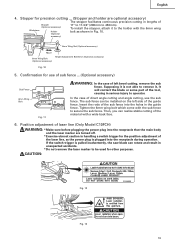
Supposing it is pulled inadvertently, the saw blade can rotate and result in unexpected accidents. * Do not remove the laser marker to 450mm). Insert the rods of Stopper (Optional accessory) Workpiece Holder (... be used for precision cutting ... (Stopper and holder are turned off. * Exercise utmost caution in Fig. 10. 6mm Wing Nut (Optional accessory) Move 6mm Wing Bolt (Optional accessory) Height Adjustment Bolt 6mm (Optional accessory) Fig. 10 5. Tighten the 6mm wing bolt which come with a wide back face. 6. CAUTION: Fig. 12 Fig. 13...
Supposing it is pulled inadvertently, the saw blade can rotate and result in unexpected accidents. * Do not remove the laser marker to 450mm). Insert the rods of Stopper (Optional accessory) Workpiece Holder (... be used for precision cutting ... (Stopper and holder are turned off. * Exercise utmost caution in Fig. 10. 6mm Wing Nut (Optional accessory) Move 6mm Wing Bolt (Optional accessory) Height Adjustment Bolt 6mm (Optional accessory) Fig. 10 5. Tighten the 6mm wing bolt which come with a wide back face. 6. CAUTION: Fig. 12 Fig. 13...

Operating Instructions
Page 21
.... Confirm the bolt has been properly tightened before performing any maintenance or inspection of the gear case (see Fig. 1) are 10" (255mm) in diameter. WARNING: When mounting the saw blade, confirm that the spindle lock has returned to the retract position after lifting the safety cover. CAUTION: * Confirm that the rotation indicator...
.... Confirm the bolt has been properly tightened before performing any maintenance or inspection of the gear case (see Fig. 1) are 10" (255mm) in diameter. WARNING: When mounting the saw blade, confirm that the spindle lock has returned to the retract position after lifting the safety cover. CAUTION: * Confirm that the rotation indicator...

Parts List
Page 1
E946 ELECTRIC TOOL PARTS LIST COMPOUND SAW Model C 10FCE2 2006 • 10 • 11 (E1) 4 5 6 7 13 14 46 47 48 49 50 3 9 8 12 11 10 22 23 24 25 26 21 15 16 39 40 41 42 43 44 45 18 19 20 38 27 28 29 53 54 55 56 57 51 52 58 602 603 604 601 605 606 30 607 31 608 32 33 34 35 36 37 628 601 609 59 63 60 64 61 62 614 615 616 618 617 46 47 48 65 629 615 619 626 627 619 620 613 609 612 611 610 621 622 623 67 626 624 627 66 625 Hitachi Power Tools LIST NO.
E946 ELECTRIC TOOL PARTS LIST COMPOUND SAW Model C 10FCE2 2006 • 10 • 11 (E1) 4 5 6 7 13 14 46 47 48 49 50 3 9 8 12 11 10 22 23 24 25 26 21 15 16 39 40 41 42 43 44 45 18 19 20 38 27 28 29 53 54 55 56 57 51 52 58 602 603 604 601 605 606 30 607 31 608 32 33 34 35 36 37 628 601 609 59 63 60 64 61 62 614 615 616 618 617 46 47 48 65 629 615 619 626 627 619 620 613 609 612 611 610 621 622 623 67 626 624 627 66 625 Hitachi Power Tools LIST NO.

Parts List
Page 3
...SCREW (W/WASHERS) M6X20 (BLACK) 1 5 322-935 CLAMP LEVER 1 6 326-706 BOLT (LEFT HAND) M10 1 7 318-934 SPECIAL WASHER 1 8 322-889 SLEEVE 1 9 322-965 LINER (D) 1 10 322-890 SPRING 1 11 302-518 STOPPER PIN ASS'Y 1 INCLUD. 12 12 984-528 O-RING (P-6) 1 13 322-933 SHAFT (D) 1 14 322-934 WASHER M16 1 15... 322-888 SHAFT (C) 1 16 322-932 HINGE 1 18 322-937 LINER (B) 1 19 322-963 DUST GUIDE HOLDER 1 20 949-215 MACHINE SCREW M4X8 (10 PCS.) 1 21 303-409 NYLOCK BOLT M8X25 2 22 322-891 DUST GUIDE ASS'Y 1 INCLUD. 19, 20, 24 23 987-512 MACHINE SCREW (W/SP. WASHER) M5X16...
...SCREW (W/WASHERS) M6X20 (BLACK) 1 5 322-935 CLAMP LEVER 1 6 326-706 BOLT (LEFT HAND) M10 1 7 318-934 SPECIAL WASHER 1 8 322-889 SLEEVE 1 9 322-965 LINER (D) 1 10 322-890 SPRING 1 11 302-518 STOPPER PIN ASS'Y 1 INCLUD. 12 12 984-528 O-RING (P-6) 1 13 322-933 SHAFT (D) 1 14 322-934 WASHER M16 1 15... 322-888 SHAFT (C) 1 16 322-932 HINGE 1 18 322-937 LINER (B) 1 19 322-963 DUST GUIDE HOLDER 1 20 949-215 MACHINE SCREW M4X8 (10 PCS.) 1 21 303-409 NYLOCK BOLT M8X25 2 22 322-891 DUST GUIDE ASS'Y 1 INCLUD. 19, 20, 24 23 987-512 MACHINE SCREW (W/SP. WASHER) M5X16...

Parts List
Page 4
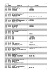
... SPINDLE AND GEAR SET 1 110 982-027 NEEDLE BEARING (HK1010) 1 111 987-512 MACHINE SCREW (W/SP. SOCKET HD. PARTS ITEM NO. SOCKET HD. BOLT M8X16 (10 PCS.) 2 62 326-826 SCALE (A) 1 63 326-696 SPACER (A) 1 64 317-200 MACHINE SCREW (W/WASHERS) M4X8 (BLACK) 1 65 326-697 FENCE (A) 1 66 322-902 ...-964 TCT SAW BLADE 255MM-D25.4 HOLE-NT100 1 * 103 974-663Z COLLAR (A) FOR D30 HOLE 1 FOR EUROPE * 103 976-819 COLLAR (B) FOR D25.4 HOLE 1 FOR AUS, INA, MAL, SIN, SYR, THA, CHN 104 323-133 SPINDLE ASS'Y 1 INCLUD. 105-109 105 990-430 SEAL LOCK FLAT HD. SCREW M6X16 (10 PCS.) 1 118...
... SPINDLE AND GEAR SET 1 110 982-027 NEEDLE BEARING (HK1010) 1 111 987-512 MACHINE SCREW (W/SP. SOCKET HD. PARTS ITEM NO. SOCKET HD. BOLT M8X16 (10 PCS.) 2 62 326-826 SCALE (A) 1 63 326-696 SPACER (A) 1 64 317-200 MACHINE SCREW (W/WASHERS) M4X8 (BLACK) 1 65 326-697 FENCE (A) 1 66 322-902 ...-964 TCT SAW BLADE 255MM-D25.4 HOLE-NT100 1 * 103 974-663Z COLLAR (A) FOR D30 HOLE 1 FOR EUROPE * 103 976-819 COLLAR (B) FOR D25.4 HOLE 1 FOR AUS, INA, MAL, SIN, SYR, THA, CHN 104 323-133 SPINDLE ASS'Y 1 INCLUD. 105-109 105 990-430 SEAL LOCK FLAT HD. SCREW M6X16 (10 PCS.) 1 118...
Parts List
Page 5
...NO. TAPPING SCREW D5X50 2 * 176 340-686D STATOR ASS'Y 110V 1 INCLUD. 177 10 -- 06 * ALTERNATIVE PARTS --- 5 --- PARTS ITEM NO. DESCRIPTION NO. HD. USED ...137 323-985 STOP PLATE 1 FOR EUROPE 138 949-454 SPRING WASHER M5 (10 PCS.) 1 139 949-215 MACHINE SCREW M4X8 (10 PCS.) 3 140 949-429 BOLT WASHER M4 (10 PCS.) 3 141 326-707 PROTECTIVE COVER 1 * 142 323-980 LINK ...FOR AUS * 154 500-456Z CORD 1 FOR CHN 155 940-778 CORD ARMOR D10.7 1 * 158 959-141 CONNECTOR 50092 (10 PCS.) 2 FOR USA, CAN * 159 958-308Z PILLAR TERMINAL (A) 1 EXCEPT FOR USA, CAN * 160 326-709 NOISE ...
...NO. TAPPING SCREW D5X50 2 * 176 340-686D STATOR ASS'Y 110V 1 INCLUD. 177 10 -- 06 * ALTERNATIVE PARTS --- 5 --- PARTS ITEM NO. DESCRIPTION NO. HD. USED ...137 323-985 STOP PLATE 1 FOR EUROPE 138 949-454 SPRING WASHER M5 (10 PCS.) 1 139 949-215 MACHINE SCREW M4X8 (10 PCS.) 3 140 949-429 BOLT WASHER M4 (10 PCS.) 3 141 326-707 PROTECTIVE COVER 1 * 142 323-980 LINK ...FOR AUS * 154 500-456Z CORD 1 FOR CHN 155 940-778 CORD ARMOR D10.7 1 * 158 959-141 CONNECTOR 50092 (10 PCS.) 2 FOR USA, CAN * 159 958-308Z PILLAR TERMINAL (A) 1 EXCEPT FOR USA, CAN * 160 326-709 NOISE ...

Parts List
Page 6
... (1 PAIR) 2 FOR 110V-120V * 182 999-065 CARBON BRUSH (1 PAIR) 2 FOR 220V-240V 183 945-161 BRUSH CAP 2 * 184 322-949 LINK 1 C 10FCE2 --- 6 --- * ALTERNATIVE PARTS 10 -- 06 PARTS ITEM NO. CODE NO.
... (1 PAIR) 2 FOR 110V-120V * 182 999-065 CARBON BRUSH (1 PAIR) 2 FOR 220V-240V 183 945-161 BRUSH CAP 2 * 184 322-949 LINK 1 C 10FCE2 --- 6 --- * ALTERNATIVE PARTS 10 -- 06 PARTS ITEM NO. CODE NO.
Parts List
Page 7
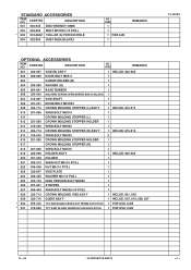
...322-710 GUIDE ASS'Y 1 INCLUD. 615, 619, 626, 627 * 630 976-472 TCT SAW BLADE CROSS-CUT 255MM-D15.9 HOLE 1 FOR USA, CAN * 631 319-658 TCT SAW BLADE 255MM-D15.88 HOLE-NT100 1 FOR USA, CAN C 10FCE2 10 -- 06 * ALTERNATIVE PARTS --- 7 --- CODE NO. DESCRIPTION NO. DESCRIPTION 501 940-543 BOX... WRENCH 10MM 502 949-695 BOLT M10X35 (10 PCS.) * 503 974-663Z COLLAR (A) FOR D30 HOLE 504 ...
...322-710 GUIDE ASS'Y 1 INCLUD. 615, 619, 626, 627 * 630 976-472 TCT SAW BLADE CROSS-CUT 255MM-D15.9 HOLE 1 FOR USA, CAN * 631 319-658 TCT SAW BLADE 255MM-D15.88 HOLE-NT100 1 FOR USA, CAN C 10FCE2 10 -- 06 * ALTERNATIVE PARTS --- 7 --- CODE NO. DESCRIPTION NO. DESCRIPTION 501 940-543 BOX... WRENCH 10MM 502 949-695 BOLT M10X35 (10 PCS.) * 503 974-663Z COLLAR (A) FOR D30 HOLE 504 ...

Parts List
Page 8
USED REMARKS C 10FCE2 --- 8 --- Printed in Japan 10 -- 06 (061011N) ITEM NO. CODE NO. DESCRIPTION NO.
USED REMARKS C 10FCE2 --- 8 --- Printed in Japan 10 -- 06 (061011N) ITEM NO. CODE NO. DESCRIPTION NO.


