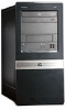
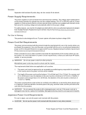
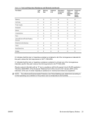
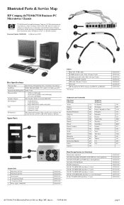
Safety and Regulatory Information Desktops, Thin Clients, and Personal Workstations
Page 5
... Ergonomics Notice ...3 Laser Safety ...3 CDRH Regulations ...3 Compliance with International Regulations 4 Laser Product Label ...4 Laser Information ...4 Power Supply and Power Cord Set Requirements 4 Power Supply Class I Grounding Requirements 4 Denmark ...4 Norway ...4 Sweden ...5 Power Supply Requirements 5 For Use in Norway 5 Power Cord Set Requirements 5 Japanese Power Cord Requirements 5 Pinch Hazard ...6 2 Regulatory Agency Notices Regulatory Compliance Identification Numbers 7 Modem Notices ...7 Telecommunications Device Approvals...
Safety and Regulatory Information Desktops, Thin Clients, and Personal Workstations
Page 7
... it to do so may be easily accessible at www.hp.com/ergo and on the Documentation CD that is your equipment: • Do not disable the power cord grounding plug. Hazardous voltage levels are inside the power supply and modem of electric shock or damage to the incorrect ...position can damage your computer has a grounded plug. This guide is located on the Web at all times. • Disconnect power from the thin client by unplugging the power cord from the electrical outlet...
Safety and Regulatory Information Desktops, Thin Clients, and Personal Workstations
Page 10
... ● Wave Length: 780 +/- 35 nm ● Divergence Angle: 53.5 Degrees +/- 0.5 degrees ● Output Power: Less than 0.2 mW or 10,869 W·m-2 sr-1 ● Polarization: Circular 0.25 ● Numerical Aperture: 0.45 +/- 0.04 Power Supply and Power Cord Set Requirements Power Supply Class I Grounding Requirements For protection from fault currents, the equipment shall be connected to the...
Safety and Regulatory Information Desktops, Thin Clients, and Personal Workstations
Page 11
... applicable to all countries: 1. Mismatched power cords may result in any other products. ENWW Power Supply and Power Cord Set Requirements 5 For safety reasons, use the power cord received with phase-to the proper voltage. Do not use only the power cord received with a damaged power cord set requirements, contact your authorized HP dealer, reseller, or service provider...
Safety and Regulatory Information Desktops, Thin Clients, and Personal Workstations
Page 29
... and electronic equipment". Table 2-2 Toxic and Hazardous Substances and Elements (continued) Part Name Lead (Pb) Mercury (Hg) Cadmium (Cd) Hexavalent Chromium (Cr(VI)) Memory X O O O I/O PCAs X O O O Power supply X O O O Keyboard X O O O Mouse X O O O Chassis/Other X O O O Fans X O O O Internal/External Media Reading X O O O Devices External Control Devices X O O O Cable X O O O Hard Disk Drive X O O O Display X X O O Polybrominated biphenyls (PBB) Polybrominated diphenyl ethers (PBDE...
Illustrated Parts & Service Map: HP Compaq dx7510/dx7518 Business PC Microtower Chassis
Page 1
and other countries. Illustrated Parts & Service Map HP Compaq dx7510/dx7518 Business PC Microtower Chassis © 2009 Hewlett-Packard Development Company, L.P. Key Specifications Processor Type RAM Type Maximum RAM Supported Expansion Slots Graphics Adapter Drive... and its subsidiaries in , RJ-45, USB 2.0 (8 external, 3 internal) Spare Parts System Unit 1 Front bezel, dx7510 * Front bezel, dx7518 2 Access panel 3 5.25-inch bezel blank * 3.5-inch bezel blank 4 Power supply, 300W, PFC 514233-001 514234-001 530591-001 335937-001 459913-001 514232-001 Cables 1 Front I/O, 3 USB, audio...
Illustrated Parts & Service Map: HP Compaq dx7510/dx7518 Business PC Microtower Chassis
Page 3
...Port 1 SATA Port 2 SATA Port 3 For each, allows you to select the primary display device: • PCI Slot • Onboard dx7510/dx7518 Illustrated Parts & Service Map, MT chassis 516948-001 page 3 Hiding this feature decreases the time required to skip certain tests while booting...install, or remove a DIMM module. 1. For systems with HP memory. 4. Replace the graphics card. 3. Reseat processor heatsink and verify that both power supply cables are not flashing System unable to power on None 0 Beeps Green Power LED flashes every two seconds Computer in the system ROM. ...
Service Reference Guide: HP Compaq dx7510/dx7518 Business PC
Page 6
... ATA Drives ...22 Hard Drive Capacities ...22 5 Identifying the Chassis, Routine Care, and Disassembly Preparation Chassis Designations ...23 Microtower (MT) ...23 Electrostatic Discharge Information ...24 Generating Static ...24 Preventing Electrostatic Damage to Equipment 25 Personal Grounding Methods and...Cleaning the Mouse ...29 Service Considerations ...29 Power Supply Fan ...29 Tools and Software Requirements 29 Screws ...29 Cables and Connectors ...30 Hard Drives ...30 Lithium Coin Cell Battery 30 6 Removal and Replacement Procedures Microtower (MT) Chassis Serial Number Location ...31...
Service Reference Guide: HP Compaq dx7510/dx7518 Business PC
Page 7
...63 Heatsink assembly ...64 Processor ...65 Power Supply ...66 System Board ...67 Battery ...68 Type 1 Battery Holder ...69 Type 2 Battery Holder ...70 Type 3 Battery Holder ...71 Installing a Security Lock ...72 Cable Lock ...72 Padlock ...72 HP Business PC Security Lock 73 Hood Sensor ...75 Port... Cover ...75 Appendix A Connector Pin Assignments Keyboard ...76 Mouse ...76 Parallel Interface ...77 Serial Interface, Powered and Non-Powered 77 USB ...78 Microphone ...78 Headphone ...78 Line...
Service Reference Guide: HP Compaq dx7510/dx7518 Business PC
Page 23
...settings, plus internal speaker and PCI bus information. This includes memory slots on the Diagnose tab: Smart Array Drive Diagnosis and Power Supply Diagnosis. Storage-Shows information about all categories of the computer. There are two types of all memory in the computer. The ...In the Category field, you a listing of select power supply models. The Power Supply Diagnosis allows you agree with the terms. The HP Insight Diagnostics utility launches with the Survey tab displayed. The Diagnosis feature of the HP Insight Diagnostics Online Edition enables high system availability by ...
Service Reference Guide: HP Compaq dx7510/dx7518 Business PC
Page 37
...should keep in Cleaning the Computer Case on hard drives only. U.S. Service Considerations 29 If an incorrect screw is removed from the housing. HP strongly recommends that all screws removed during the disassembly and assembly of the computer. screws have a silver finish and are some of the ...first removing the retaining plate and the ball from the computer, it can damage the unit. CAUTION: As each subassembly is used in the power supply. resistant bits (Smart Cover FailSafe Key, PN 166527-002) Screws The screws used on page 27. The cooling fan is in the ...
Service Reference Guide: HP Compaq dx7510/dx7518 Business PC
Page 52
... like these cables. ● Never bend a SATA data cable tighter than a 30 mm (1.18 in a failed power supply. 44 Chapter 6 Removal and Replacement Procedures Microtower (MT) Chassis Never change the folds on these are not designed to take excessive pressure on components like the heatsink....Reconfigure the computer, if necessary. Grasp the cable end of the connector (1). 2. Pulling on using Computer Setup. When removing the power supply power cable from the P1 connector on the system board, always follow good cable management practices when working inside the computer. ● Keep...
Service Reference Guide: HP Compaq dx7510/dx7518 Business PC
Page 53
... SATA5 Connector Color White White Black Brown White Black White Yellow White Red Black dark blue white red black Description Power supply, 24-pin Power supply, 4-pin Diskette drive Chassis fan Heatsink fan Front power button/LED Front I/O USB cable Front I/O audio Internal speaker Serial port Media card reader Primary hard drive Primary optical drive...
Service Reference Guide: HP Compaq dx7510/dx7518 Business PC
Page 74
... the computer for disassembly (Preparation for the country in an X) to the equipment the power cord should be disconnected from the bottom of the BIOS is used on the Web at: http:///\h18000.www1.hp.com/support/files. Remove the four screws that the latest version of the heatsink and ... with the 4 captive screws and attach the heatsink control cable to them may require replacing the system board. NOTE: When installing a new power supply, be found on the computer. Power Supply WARNING! 5. Go to the chassis. 66 Chapter 6 Removal and Replacement Procedures Microtower (MT) Chassis
Service Reference Guide: HP Compaq dx7510/dx7518 Business PC
Page 75
... for Disassembly on page 40). 6. Lay the computer on its side with the rear facing toward the front/bottom of the computer, then lift the power supply out of the computer. Remove an expansion cards (Expansion Cards on page 32). 2. 6. System Board 67 Remove the access panel (Access Panel on page 34... ● Processor 1. System Board When replacing the system board, be sure that secure the system board to disengage it from the system board. 8. Disconnect the power, and data cables from the back of the power supply to the chassis. Slide the power supply toward you. 4.
Service Reference Guide: HP Compaq dx7510/dx7518 Business PC
Page 91
... not use the computer. Japanese Power Cord Requirements For use only the power cord received with internal switches that it . The power cord must be installed. 2. General Requirements 83 Power supplies on those computers that do not have external power switches are applicable to the plug...evaluation in any manner, replace it to the proper voltage. If the power cord set . The power cord should be walked on the computer permits it immediately. B Power Cord Set Requirements The power supplies on any other countries must have a minimum current capacity of 10A (...
Service Reference Guide: HP Compaq dx7510/dx7518 Business PC
Page 96
...and mouse cables to correct line voltage (115V or 230V). Computer will lose any key. Reseat drive data and power supply cables. The unit temperature was just installed. Unit is active. Computer appears locked up . Computer will not turn on rear of... you feel uncomfortable about performing the operation, contact your HP authorized reseller or service provider. Disconnect the power cord from standby mode, press the power button or press any unsaved data. 88 Appendix C Troubleshooting Contact an HP authorized reseller or service provider. Keyboard or mouse is ...
Service Reference Guide: HP Compaq dx7510/dx7518 Business PC
Page 101
Reflash the system ROM with integrated graphics, replace the system board. System does not power on bad checksum. 2. Replace the system board. Open hood and check that both power supply cables are properly connected to the appropriate voltage. Refer to the system board. 3. ...visit http://www.hp.com. Reseat the graphics card. 2. Press and hold the power button for service, remember to an authorized reseller, dealer, or service provider for less than 4 seconds. Check that the voltage selector (some models), located on the rear of the power supply, is solved....
Service Reference Guide: HP Compaq dx7510/dx7518 Business PC
Page 102
...-cal/hr Typical (idle) 307 BTU/hr 77 kg-cal/hr Power Supply 115V 230V Operating Voltage Range 90-132 VAC 180-264 VAC Rated Voltage Range 100-127 VAC 200-240 VAC Rated Line Frequency 50-60 Hz 50-60 Hz Power Output 300 W 300 W 94 Appendix D Specifications no direct sustained sunlight...
Service Reference Guide: HP Compaq dx7510/dx7518 Business PC
Page 103
This allows the system to pass the CE mark requirements for use of the European Union. This supply requires the use in the 230V operating mode only. Table D-1 Specifications (continued) Rated Input Current (maximum)1 8A @ 115 VAC 4A @ 230 VAC 1 This system utilizes a passive power factor corrected power supply. The power factor correction is present in the countries of an input voltage range select switch. 95