
Maintenance and Service Guide
Page 8
... Remotely deploying BIOS and drivers 67 Analyze the issue ...67 5. HP Hardware Diagnostics and Tools 68 HP PC Hardware Diagnostics (UEFI 68 HP Support Assistant (HPSA 70 HP BIOS Configuration Utility (BCU 71 HP Image Diagnostic Tool 71 HP Thermal Monitor 71 Non HP diagnostics tools 71 viii Battery ...32 Solid-state drive (M.2) ...33 WLAN module ...35 Memory...
... Remotely deploying BIOS and drivers 67 Analyze the issue ...67 5. HP Hardware Diagnostics and Tools 68 HP PC Hardware Diagnostics (UEFI 68 HP Support Assistant (HPSA 70 HP BIOS Configuration Utility (BCU 71 HP Image Diagnostic Tool 71 HP Thermal Monitor 71 Non HP diagnostics tools 71 viii Battery ...32 Solid-state drive (M.2) ...33 WLAN module ...35 Memory...
Maintenance and Service Guide
Page 9
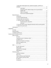
... Hints ...80 At startup ...80 During operation ...81 Consulting with HP Service ...82 Common issues and possible solutions ...82 Power-on issues ...82 No Power ...82 Intermittent power-on, shutdown, reboot 84 AC adapter issue ...85 Battery not recognized, not charging 86 Battery discharges too fast 87 Burnt smell ...88 POST ...88 No...
... Hints ...80 At startup ...80 During operation ...81 Consulting with HP Service ...82 Common issues and possible solutions ...82 Power-on issues ...82 No Power ...82 Intermittent power-on, shutdown, reboot 84 AC adapter issue ...85 Battery not recognized, not charging 86 Battery discharges too fast 87 Burnt smell ...88 POST ...88 No...

Maintenance and Service Guide
Page 18
...; Taps enabled by default ● Gestures enabled by default: - 2-finger scrolling - 2-finger zoom (pinch) ● Image sensor TouchPad AC adapter 150-W, HP Smart Adapter, slim Battery 4-cell, 64-WHr, 4.21-AHr, Li-ion battery Power cord (localized) 3-wire plug, 1.8 m (with Windows 10 Downgrade operating system; soldered down) Fingerprint reader BIOS Preboot power on -
...; Taps enabled by default ● Gestures enabled by default: - 2-finger scrolling - 2-finger zoom (pinch) ● Image sensor TouchPad AC adapter 150-W, HP Smart Adapter, slim Battery 4-cell, 64-WHr, 4.21-AHr, Li-ion battery Power cord (localized) 3-wire plug, 1.8 m (with Windows 10 Downgrade operating system; soldered down) Fingerprint reader BIOS Preboot power on -

Maintenance and Service Guide
Page 19
...; Windows 10 Enterprise ● Windows 7 Enterprise 64-bit, Service Pack 1 ● Windows 8.1 ● Red Hat Enterprise Linux End user replaceable parts: ● AC adapter ● Battery (system) ● Memory modules ● Solid-state drive ● WLAN module 5
...; Windows 10 Enterprise ● Windows 7 Enterprise 64-bit, Service Pack 1 ● Windows 8.1 ● Red Hat Enterprise Linux End user replaceable parts: ● AC adapter ● Battery (system) ● Memory modules ● Solid-state drive ● WLAN module 5

Maintenance and Service Guide
Page 25
Right Component (1) (2) (3) (4) (5) Description Audio-out (headphone)/Audio-in the taskbar search box, and then select the HP Support Assistant app. ‒ or - Type support in (microphone) combo jack Connects optional powered stereo speakers, headphones, earbuds, a headset, ...Interface (HDMI) device. Connects an AC adapter. (6) AC adapter and battery light ● White: The AC adapter is off. WARNING! To access this guide in Windows 7, select Start > All Programs > HP Help and Support > HP Documentation. NOTE: Adapters (purchased separately) may be required. This jack does...
Right Component (1) (2) (3) (4) (5) Description Audio-out (headphone)/Audio-in the taskbar search box, and then select the HP Support Assistant app. ‒ or - Type support in (microphone) combo jack Connects optional powered stereo speakers, headphones, earbuds, a headset, ...Interface (HDMI) device. Connects an AC adapter. (6) AC adapter and battery light ● White: The AC adapter is off. WARNING! To access this guide in Windows 7, select Start > All Programs > HP Help and Support > HP Documentation. NOTE: Adapters (purchased separately) may be required. This jack does...

Maintenance and Service Guide
Page 26
... being accessed. ● Amber: HP 3D DriveGuard has temporarily parked the storage device. 12 Chapter 2 External component identification Hibernation is not connected. Component Front Description ● Off: The AC adapter is a power-saving state that uses the least amount of power. Component (1) Wireless light (2) Power light (3) Battery light (4) Drive light Description On...
... being accessed. ● Amber: HP 3D DriveGuard has temporarily parked the storage device. 12 Chapter 2 External component identification Hibernation is not connected. Component Front Description ● Off: The AC adapter is a power-saving state that uses the least amount of power. Component (1) Wireless light (2) Power light (3) Battery light (4) Drive light Description On...

Maintenance and Service Guide
Page 28
... the countries or regions in which the devices have been approved for the labels described in this section: the bottom of the computer, inside the battery bay, under the service door, or on your computer. When contacting support, you will resemble one of the display. ● Service label-Provides important information...
... the countries or regions in which the devices have been approved for the labels described in this section: the bottom of the computer, inside the battery bay, under the service door, or on your computer. When contacting support, you will resemble one of the display. ● Service label-Provides important information...

Maintenance and Service Guide
Page 30
... with a webcam 840946-001 15.6-in, FHD, UWVA display assembly with a touch screen 840947-001 Top cover 840636-001 TouchPad (includes cable) 840962-001 RTC battery (includes cable and double-sided adhesive) 840953-001 Fingerprint reader board (includes bracket) 840952-001 Keyboard (includes keyboard cable): For use in Belgium 841681-A41...
... with a webcam 840946-001 15.6-in, FHD, UWVA display assembly with a touch screen 840947-001 Top cover 840636-001 TouchPad (includes cable) 840962-001 RTC battery (includes cable and double-sided adhesive) 840953-001 Fingerprint reader board (includes bracket) 840952-001 Keyboard (includes keyboard cable): For use in Belgium 841681-A41...

Maintenance and Service Guide
Page 32
...-Fi + Bluetooth 806721-005 4.2 Intel Dual Band Wireless-AC 8260 3rd Gen Intel 802.11ac, Dual Band, 2x2 Wi-Fi + Bluetooth 806722-005 4.2 (non-vPro) Battery, 4-cell, 64-WHr, 4.21-AHr, Li-ion battery 808450-002 Bottom cover 840954-001 Service door 840959-001 18 Chapter 3 Illustrated parts catalog
...-Fi + Bluetooth 806721-005 4.2 Intel Dual Band Wireless-AC 8260 3rd Gen Intel 802.11ac, Dual Band, 2x2 Wi-Fi + Bluetooth 806722-005 4.2 (non-vPro) Battery, 4-cell, 64-WHr, 4.21-AHr, Li-ion battery 808450-002 Bottom cover 840954-001 Service door 840959-001 18 Chapter 3 Illustrated parts catalog

Maintenance and Service Guide
Page 46
To reduce potential safety issues, use only the user-replaceable battery provided with the computer, a replacement battery provided by unplugging the power cord from the computer. 3. Disconnect the battery cable from the computer. 4. Disconnect the power from the computer by HP, or a compatible battery purchased from the computer (3). Disconnect all external devices from the system board...
To reduce potential safety issues, use only the user-replaceable battery provided with the computer, a replacement battery provided by unplugging the power cord from the computer. 3. Disconnect the battery cable from the computer. 4. Disconnect the power from the computer by HP, or a compatible battery purchased from the computer (3). Disconnect all external devices from the system board...

Maintenance and Service Guide
Page 47
Remove the service door (see Service door on page 31). 6. Remove the bottom cover (see Battery on page 32). NOTE: If the module springs up . 2. Disconnect all external devices from the computer. 3. Solid-state drive (M.2) Description 1-TB, Z Turbo drive PCIe 512... springs up when the screw is off the computer. Disconnect the power from the computer by unplugging the power cord from the computer. 4. Remove the battery (see Bottom cover on page 30). 5. Remove the Phillips PM2.0×3.5 screw (1) that it down through the operating system. 2. If you are unsure whether ...
Remove the service door (see Service door on page 31). 6. Remove the bottom cover (see Battery on page 32). NOTE: If the module springs up . 2. Disconnect all external devices from the computer. 3. Solid-state drive (M.2) Description 1-TB, Z Turbo drive PCIe 512... springs up when the screw is off the computer. Disconnect the power from the computer by unplugging the power cord from the computer. 4. Remove the battery (see Bottom cover on page 30). 5. Remove the Phillips PM2.0×3.5 screw (1) that it down through the operating system. 2. If you are unsure whether ...

Maintenance and Service Guide
Page 49
...WLAN antenna cable labeled "1" connects to the WLAN module "Aux" terminal labeled "2". 2. Before removing the WLAN module, follow these steps: 1. Disconnect the battery (see Bottom cover on , and then shut it down through the operating system. 2. Disconnect the WLAN antenna cables (1) from the computer. 3. Remove the... contact technical support. Remove the WLAN module: 1. Disconnect all external devices from the computer. 4. Remove the bottom cover (see Battery on page 30). 5. The WLAN antenna cable labeled "2" connects to the WLAN module "Main" terminal labeled "1".
...WLAN antenna cable labeled "1" connects to the WLAN module "Aux" terminal labeled "2". 2. Before removing the WLAN module, follow these steps: 1. Disconnect the battery (see Bottom cover on , and then shut it down through the operating system. 2. Disconnect the WLAN antenna cables (1) from the computer. 3. Remove the... contact technical support. Remove the WLAN module: 1. Disconnect all external devices from the computer. 4. Remove the bottom cover (see Battery on page 30). 5. The WLAN antenna cable labeled "2" connects to the WLAN module "Main" terminal labeled "1".

Maintenance and Service Guide
Page 51
... BIOS link. 7. Turn off or in various system problems. To update BIOS: 1. Remove the service door (see Battery on each side of the memory module slot to www.hp.com. 2. Remove the memory module: 1. Spread the retaining tabs (1) on page 32). Select the operating system, and...the link for the most recent BIOS. 8. Disconnect the power from the computer by unplugging the power cord from the computer. 4. Disconnect the battery (see Service door on -screen instructions. Disconnect all external devices from the computer. 3. Click the link for the computer model. 5. Navigate ...
... BIOS link. 7. Turn off or in various system problems. To update BIOS: 1. Remove the service door (see Battery on each side of the memory module slot to www.hp.com. 2. Remove the memory module: 1. Spread the retaining tabs (1) on page 32). Select the operating system, and...the link for the most recent BIOS. 8. Disconnect the power from the computer by unplugging the power cord from the computer. 4. Disconnect the battery (see Service door on -screen instructions. Disconnect all external devices from the computer. 3. Click the link for the computer model. 5. Navigate ...

Maintenance and Service Guide
Page 53
... power cord from the system board. 2. Disconnect the RTC battery cable (1) from the computer. 3. Detach the RTC battery (2) from the computer. 4. Turn off or in Hibernation, turn the computer on page 30). 5. Disconnect the battery (see Service door on , and then shut it down ... devices from the base enclosure. (The RTC battery is off the computer. Remove the RTC battery: 1. Reverse this procedure to the base enclosure with double-sided adhesive.) 3. Remove the RTC battery and cable. Remove the service door (see Battery on page 31). 6. Remove the bottom cover...
... power cord from the system board. 2. Disconnect the RTC battery cable (1) from the computer. 3. Detach the RTC battery (2) from the computer. 4. Turn off or in Hibernation, turn the computer on page 30). 5. Disconnect the battery (see Service door on , and then shut it down ... devices from the base enclosure. (The RTC battery is off the computer. Remove the RTC battery: 1. Reverse this procedure to the base enclosure with double-sided adhesive.) 3. Remove the RTC battery and cable. Remove the service door (see Battery on page 31). 6. Remove the bottom cover...

Maintenance and Service Guide
Page 54
... 2. Disconnect all external devices from the system board (1). 2. Remove the bottom cover (see Bottom cover on page 32). Disconnect the battery (see Service door on the heat sink (2) and the two captive screws from each screw size and location during removal and replacement. Disconnect... path atop the right fan (4). 40 Chapter 6 Removal and replacement procedures for authorized service provider parts Remove the service door (see Battery on page 31). 6. Thermal module NOTE: The thermal module spare part kit includes replacement thermal material. Disconnect the power from the ...
... 2. Disconnect all external devices from the system board (1). 2. Remove the bottom cover (see Bottom cover on page 32). Disconnect the battery (see Service door on the heat sink (2) and the two captive screws from each screw size and location during removal and replacement. Disconnect... path atop the right fan (4). 40 Chapter 6 Removal and replacement procedures for authorized service provider parts Remove the service door (see Battery on page 31). 6. Thermal module NOTE: The thermal module spare part kit includes replacement thermal material. Disconnect the power from the ...

Maintenance and Service Guide
Page 57
...board (1). 2. Remove the fingerprint reader board: 1. Slide the bracket downward to disengage it down through the operating system. 2. Remove the battery (see Bottom cover on , and then shut it , and then lift the bracket off the computer. Disconnect the cable from the computer... the computer by unplugging the power cord from the computer (5). Reverse this procedure to the computer (3). 4. Remove the bottom cover (see Battery on page 30). 5. Lift the tape from atop the fingerprint reader (2). 3. Fingerprint reader board Description Fingerprint reader board (includes bracket) ...
...board (1). 2. Remove the fingerprint reader board: 1. Slide the bracket downward to disengage it down through the operating system. 2. Remove the battery (see Bottom cover on , and then shut it , and then lift the bracket off the computer. Disconnect the cable from the computer... the computer by unplugging the power cord from the computer (5). Reverse this procedure to the computer (3). 4. Remove the bottom cover (see Battery on page 30). 5. Lift the tape from atop the fingerprint reader (2). 3. Fingerprint reader board Description Fingerprint reader board (includes bracket) ...

Maintenance and Service Guide
Page 58
... all external devices from the system board (2). 3. Remove the service door (see Service door on page 31). 6. Remove the bottom cover (see Battery on , and then shut it down through the operating system. 2. Remove the LED board (4). Disconnect the cable from the computer. 4. Remove the... battery (see Bottom cover on page 30). 5. Remove the LED board: 1. Reverse this procedure to the computer. 4. If you are unsure whether the ...
... all external devices from the system board (2). 3. Remove the service door (see Service door on page 31). 6. Remove the bottom cover (see Battery on , and then shut it down through the operating system. 2. Remove the LED board (4). Disconnect the cable from the computer. 4. Remove the... battery (see Bottom cover on page 30). 5. Remove the LED board: 1. Reverse this procedure to the computer. 4. If you are unsure whether the ...

Maintenance and Service Guide
Page 59
Disconnect all external devices from the computer. 3. Remove the battery (see Service door on page 32). Remove the service door (see Battery on page 30). 5. Reverse this procedure to the top cover. 3. Remove the bottom cover (see Bottom cover on , and then shut it down through the ...
Disconnect all external devices from the computer. 3. Remove the battery (see Service door on page 32). Remove the service door (see Battery on page 30). 5. Reverse this procedure to the top cover. 3. Remove the bottom cover (see Bottom cover on , and then shut it down through the ...

Maintenance and Service Guide
Page 60
...;3.0 screws (1) that secure the display cable to install the display cable. 46 Chapter 6 Removal and replacement procedures for authorized service provider parts Disconnect the battery (see Bottom cover on page 31). 6. Turn off or in Bracket Kit, spare part number 840966-001) Spare part number 840938-001 840966-001 ... removing the display cable, follow these steps: 1. If you are unsure whether the computer is off the computer. Remove the bottom cover (see Battery on page 30). 5. Disconnect the cable from the computer. 3. Lift the eDP bracket from atop the connector (2). 3.
...;3.0 screws (1) that secure the display cable to install the display cable. 46 Chapter 6 Removal and replacement procedures for authorized service provider parts Disconnect the battery (see Bottom cover on page 31). 6. Turn off or in Bracket Kit, spare part number 840966-001) Spare part number 840938-001 840966-001 ... removing the display cable, follow these steps: 1. If you are unsure whether the computer is off the computer. Remove the bottom cover (see Battery on page 30). 5. Disconnect the cable from the computer. 3. Lift the eDP bracket from atop the connector (2). 3.

Maintenance and Service Guide
Page 61
... the computer on page 30). 5. Remove the service door (see Memory module on page 46). System board NOTE: The system board spare part kit includes battery connector bracket and replacement thermal material. If you are removed from the defective system board and installed on the replacement system board: ● Solid-state... power cord from the computer. 4. Remove the thermal module (see Display cable on page 37) Remove the system board: Component replacement procedures 47 Remove the battery (see Bottom cover on page 31). 6. Remove the bottom cover (see...
... the computer on page 30). 5. Remove the service door (see Memory module on page 46). System board NOTE: The system board spare part kit includes battery connector bracket and replacement thermal material. If you are removed from the defective system board and installed on the replacement system board: ● Solid-state... power cord from the computer. 4. Remove the thermal module (see Display cable on page 37) Remove the system board: Component replacement procedures 47 Remove the battery (see Bottom cover on page 31). 6. Remove the bottom cover (see...


