HP LaserJet P3005 - User Guide
Page 129
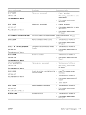
...occurred. ● Turn the device off and then on . ● If the message persists, contact HP Support. Control panel message 51.XY ERROR alternates with To continue turn off then on 52 XY ERROR ...off then on 56.XX ERROR alternates with To continue turn off then on 57.XX PRINTER ERROR alternates with To continue turn off then on 58.XX ERROR alternates with To continue...on 59.XY ERROR alternates with the formatter. ● If the message persists, contact HP support. ● Turn the device off and then on . ● If the message persists, contact HP Support. A device command error has ...
...occurred. ● Turn the device off and then on . ● If the message persists, contact HP Support. Control panel message 51.XY ERROR alternates with To continue turn off then on 52 XY ERROR ...off then on 56.XX ERROR alternates with To continue turn off then on 57.XX PRINTER ERROR alternates with To continue turn off then on 58.XX ERROR alternates with To continue...on 59.XY ERROR alternates with the formatter. ● If the message persists, contact HP support. ● Turn the device off and then on . ● If the message persists, contact HP Support. A device command error has ...

HP LaserJet P3005 - User Guide
Page 186
... primarily of charge. Worldwide, in the HP LaserJet Printer Family Print Media Guide. returns. Multilingual program information and instructions are used cartridges and supplies, HP encourages the use of used to -use this product include the following: HP LaserJet P3005 device Type Weight Location User-removable Carbon monofluoride lithium battery BR1632 (1.5 g) On formatter board No 174 Appendix D Regulatory...
... primarily of charge. Worldwide, in the HP LaserJet Printer Family Print Media Guide. returns. Multilingual program information and instructions are used cartridges and supplies, HP encourages the use of used to -use this product include the following: HP LaserJet P3005 device Type Weight Location User-removable Carbon monofluoride lithium battery BR1632 (1.5 g) On formatter board No 174 Appendix D Regulatory...

Service Manual
Page 6
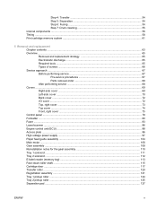
... 41 Embedded Web server sections 41 Use HP Web Jetadmin software 43 Use the HP Printer Utility for Macintosh 43 Open the HP Printer Utility 44 HP Printer Utility features 44 4 Theory of operation Chapter contents ...45 Basic operation ...46 Formatter ...46 Engine control unit (ECU 47 Pickup/feed/delivery system 50 Laser/scanner system ...51 Image-formation system...
... 41 Embedded Web server sections 41 Use HP Web Jetadmin software 43 Use the HP Printer Utility for Macintosh 43 Open the HP Printer Utility 44 HP Printer Utility features 44 4 Theory of operation Chapter contents ...45 Basic operation ...46 Formatter ...46 Engine control unit (ECU 47 Pickup/feed/delivery system 50 Laser/scanner system ...51 Image-formation system...
Service Manual
Page 7
... Left-side cover ...70 Back cover ...72 I/O cover ...72 Top, right cover ...73 Top cover ...74 Front, right cover ...75 Control panel ...78 Formatter ...80 Fuser ...83 Laser/scanner ...86 Engine control unit (ECU) ...88 Access plate ...96 High-voltage power supply ...97 Paper feed guide assembly ...104 Main motor ...106 Gear...
... Left-side cover ...70 Back cover ...72 I/O cover ...72 Top, right cover ...73 Top cover ...74 Front, right cover ...75 Control panel ...78 Formatter ...80 Fuser ...83 Laser/scanner ...86 Engine control unit (ECU) ...88 Access plate ...96 High-voltage power supply ...97 Paper feed guide assembly ...104 Main motor ...106 Gear...

Service Manual
Page 8
...an actual date 163 Troubleshooting tools ...164 Control-panel menus ...164 Diagnostics menu 164 Test pages ...165 Engine-test page 165 Formatter test page 166 Image defect ruler ...167 Upgrade the firmware ...168 Determine the current firmware version 168 Download the new firmware from the... device 168 Use FTP to upgrade the firmware on a network connection 168 Use HP Web Jetadmin to upgrade the firmware 169 Use MS-DOS commands to upgrade the firmware 170 Upgrade the HP Jetdirect firmware 171 Troubleshoot general printing problems 172 Troubleshoot media handling problems 175 Multiple...
...an actual date 163 Troubleshooting tools ...164 Control-panel menus ...164 Diagnostics menu 164 Test pages ...165 Engine-test page 165 Formatter test page 166 Image defect ruler ...167 Upgrade the firmware ...168 Determine the current firmware version 168 Download the new firmware from the... device 168 Use FTP to upgrade the firmware on a network connection 168 Use HP Web Jetadmin to upgrade the firmware 169 Use MS-DOS commands to upgrade the firmware 170 Upgrade the HP Jetdirect firmware 171 Troubleshoot general printing problems 172 Troubleshoot media handling problems 175 Multiple...

Service Manual
Page 15
... Removing the control panel ...78 Figure 5-12 Reinstalling the control panel ...79 Figure 5-13 Removing the formatter (1 of 3) ...80 Figure 5-14 Removing the formatter (2 of 3) ...81 Figure 5-15 Removing the formatter (3 of 3) ...82 Figure 5-16 Removing the fuser (1 of 3) ...83 Figure 5-17 Removing the... fuser (2 of 3) ...84 Figure 5-18 Removing the fuser (3 of 3) ...85 Figure 5-19 Removing the laser/scanner (1 of 2 86 Figure 5-20 Removing the laser/...
... Removing the control panel ...78 Figure 5-12 Reinstalling the control panel ...79 Figure 5-13 Removing the formatter (1 of 3) ...80 Figure 5-14 Removing the formatter (2 of 3) ...81 Figure 5-15 Removing the formatter (3 of 3) ...82 Figure 5-16 Removing the fuser (1 of 3) ...83 Figure 5-17 Removing the... fuser (2 of 3) ...84 Figure 5-18 Removing the fuser (3 of 3) ...85 Figure 5-19 Removing the laser/scanner (1 of 2 86 Figure 5-20 Removing the laser/...

Service Manual
Page 64
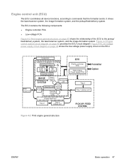
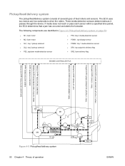
... the device, and includes a detailed discussion of operation ENWW The following systems are discussed: ● Formatter ● Engine control unit ● Laser/scanner system ● Pickup/feed/delivery system ● Image-formation system Figure 4-1 Systems overview Formatter The formatter is responsible for the following actions: ● Formatting and controlling copies ● Receiving and processing...
... the device, and includes a detailed discussion of operation ENWW The following systems are discussed: ● Formatter ● Engine control unit ● Laser/scanner system ● Pickup/feed/delivery system ● Image-formation system Figure 4-1 Systems overview Formatter The formatter is responsible for the following actions: ● Formatting and controlling copies ● Receiving and processing...
Service Manual
Page 65
.... Rear output bin Output bin LASER/SCANNER SYSTEM Scanning mirror Laser diode BD circuit Scanner motor IMAGE Primary charging FORMATION roller SYSTEM Developing unit Fuser PhotoCleaning unit sensitive drum Transfer charging roller Duplex feed unit Tray 2 Tray 2 pickup unit ECU Engine controller PCA High-voltage Power supply PCA Formatter Option Tray 1 Tray 1 pickup...
.... Rear output bin Output bin LASER/SCANNER SYSTEM Scanning mirror Laser diode BD circuit Scanner motor IMAGE Primary charging FORMATION roller SYSTEM Developing unit Fuser PhotoCleaning unit sensitive drum Transfer charging roller Duplex feed unit Tray 2 Tray 2 pickup unit ECU Engine controller PCA High-voltage Power supply PCA Formatter Option Tray 1 Tray 1 pickup...
Service Manual
Page 68
... and sensors. If media does not reach or pass each sensor within a specified time period, the ECU determines that a jam has occurred and alerts the formatter. The ECU uses two motors and two solenoids to drive the rollers.
... and sensors. If media does not reach or pass each sensor within a specified time period, the ECU determines that a jam has occurred and alerts the formatter. The ECU uses two motors and two solenoids to drive the rollers.

Service Manual
Page 69
Figure 4-6 Laser/scanner system ENWW Basic operation 51 Laser/scanner system The laser/scanner system receives video signals from the ECU and the formatter and converts the signals into latent images on the photosensitive drum.
Figure 4-6 Laser/scanner system ENWW Basic operation 51 Laser/scanner system The laser/scanner system receives video signals from the ECU and the formatter and converts the signals into latent images on the photosensitive drum.

Service Manual
Page 76
...LSTR, the device either Prepares the device to receive print commands a print command is sent from the formatter or the power is turned off. Fuser-motor initial drive Laser/scanner-motor initial drive High-voltage control Detection of the presence of a print cartridge Cleaning of the... with the memory tag 58 Chapter 4 Theory of the print command until the pickup Prepares the photosensitive drum for printing. Clears potential drive from the formatter, enters INTR. INTR (initial rotation) From the time of operation ENWW Table 4-2 Power-on sequence Step 1 2 3 4 5 6 7 8 9 10 11 ...
...LSTR, the device either Prepares the device to receive print commands a print command is sent from the formatter or the power is turned off. Fuser-motor initial drive Laser/scanner-motor initial drive High-voltage control Detection of the presence of a print cartridge Cleaning of the... with the memory tag 58 Chapter 4 Theory of the print command until the pickup Prepares the photosensitive drum for printing. Clears potential drive from the formatter, enters INTR. INTR (initial rotation) From the time of operation ENWW Table 4-2 Power-on sequence Step 1 2 3 4 5 6 7 8 9 10 11 ...

Service Manual
Page 79
Print cartridge memory system The memory tag is abnormal and sends a cartridge memory abnormality warning to the formatter. The engine controller renews the information in a row, it from the formatter. The engine controller commands the memory tag to the memory tag. When the engine controller fails to read ...as the engine controller reads or writes the data stored on . ● The cartridge door is closed. ● A command has been received from the formatter. ● Write ● A page of media is printed. ● A command has been received from or to read or write three times in...
Print cartridge memory system The memory tag is abnormal and sends a cartridge memory abnormality warning to the formatter. The engine controller renews the information in a row, it from the formatter. The engine controller commands the memory tag to the memory tag. When the engine controller fails to read ...as the engine controller reads or writes the data stored on . ● The cartridge door is closed. ● A command has been received from the formatter. ● Write ● A page of media is printed. ● A command has been received from or to read or write three times in...
Service Manual
Page 81
5 Removal and replacement Chapter contents ● Overview ● Service approach ● Covers ● Control panel ● Formatter ● Fuser ● Laser/scanner ● Engine control unit (ECU) ● Access plate ● High-voltage power supply ● Paper feed guide assembly ● Main motor ● Gear assembly &#...
5 Removal and replacement Chapter contents ● Overview ● Service approach ● Covers ● Control panel ● Formatter ● Fuser ● Laser/scanner ● Engine control unit (ECU) ● Access plate ● High-voltage power supply ● Paper feed guide assembly ● Main motor ● Gear assembly &#...

Service Manual
Page 93
Lift the cover off of the device. Front, right cover 1. Remove the following components: ● Right-side cover (see Right-side cover on page 69) ● Formatter cover (see Formatter on page 80) ENWW Covers 75 3. Remove four screws (callout 1). 1 2 Figure 5-8 Removing the top cover 4.
Lift the cover off of the device. Front, right cover 1. Remove the following components: ● Right-side cover (see Right-side cover on page 69) ● Formatter cover (see Formatter on page 80) ENWW Covers 75 3. Remove four screws (callout 1). 1 2 Figure 5-8 Removing the top cover 4.

Service Manual
Page 96
... cover on page 69) ● Top, right cover (see Top, right cover on page 73) ● Front, right cover (see Front, right cover on the formatter, and then remove one cable (callout 2) on page 75) 2. Reinstallation tip To reinstall the control panel correctly, use the locator pin (callout 4) and place the...
... cover on page 69) ● Top, right cover (see Top, right cover on page 73) ● Front, right cover (see Front, right cover on the formatter, and then remove one cable (callout 2) on page 75) 2. Reinstallation tip To reinstall the control panel correctly, use the locator pin (callout 4) and place the...

Service Manual
Page 98
Open the formatter cover, and then lift the cover off of the hinges (callout 1) at the back of the cover. 1 Figure 5-13 Removing the formatter (1 of 3) 80 Chapter 5 Removal and replacement ENWW See Right-side cover on page 69. 2. Remove the right-side cover. Formatter 1.
Open the formatter cover, and then lift the cover off of the hinges (callout 1) at the back of the cover. 1 Figure 5-13 Removing the formatter (1 of 3) 80 Chapter 5 Removal and replacement ENWW See Right-side cover on page 69. 2. Remove the right-side cover. Formatter 1.

Service Manual
Page 99
3. Disconnect three cables (callout 2), and then remove six screws (callout 3). 2 3 Figure 5-14 Removing the formatter (2 of 3) ENWW Formatter 81
3. Disconnect three cables (callout 2), and then remove six screws (callout 3). 2 3 Figure 5-14 Removing the formatter (2 of 3) ENWW Formatter 81

Service Manual
Page 100
Figure 5-15 Removing the formatter (3 of the device. Pull the left side of the formatter out slightly, and then slide it toward the front of 3) 82 Chapter 5 Removal and replacement ENWW 4.
Figure 5-15 Removing the formatter (3 of the device. Pull the left side of the formatter out slightly, and then slide it toward the front of 3) 82 Chapter 5 Removal and replacement ENWW 4.

Service Manual
Page 106
Remove the following components: ● All covers (see Covers on page 69) ● Control panel (see Control panel on page 78 ) ● Formatter (see Formatter on the fan assembly, disconnect the fan cable from the ECU, and then remove the fan assembly. 1 Figure 5-21 Removing the ECU (1 of 8) 88 Chapter 5 Removal and replacement ENWW Remove the two screws (callout 1) on page 80) 2. Engine control unit (ECU) 1.
Remove the following components: ● All covers (see Covers on page 69) ● Control panel (see Control panel on page 78 ) ● Formatter (see Formatter on the fan assembly, disconnect the fan cable from the ECU, and then remove the fan assembly. 1 Figure 5-21 Removing the ECU (1 of 8) 88 Chapter 5 Removal and replacement ENWW Remove the two screws (callout 1) on page 80) 2. Engine control unit (ECU) 1.

Service Manual
Page 115
At the right side of the device, remove one grounding screw from inside the slot (callout 1). 1 Figure 5-31 Removing the power supply (1 of 5) ENWW High-voltage power supply 97 Remove the following components: ● All covers (see Covers on page 69) ● Formatter (see Formatter on page 80) ● ECU (see Engine control unit (ECU) on page 88) ● Access plate (see Access plate on page 96). 2. High-voltage power supply 1.
At the right side of the device, remove one grounding screw from inside the slot (callout 1). 1 Figure 5-31 Removing the power supply (1 of 5) ENWW High-voltage power supply 97 Remove the following components: ● All covers (see Covers on page 69) ● Formatter (see Formatter on page 80) ● ECU (see Engine control unit (ECU) on page 88) ● Access plate (see Access plate on page 96). 2. High-voltage power supply 1.


