
HP Mini 1000 and Compaq Mini 700 - Maintenance and Service Guide
Page 38
... pack mailer or other suitable form of protective packaging and label the package "FRAGILE." 30 Chapter 4 Removal and replacement procedures While handling a drive, avoid touching the connector. After removing a hard drive, an optical drive, or a diskette drive, place it down the device. Drive ... surface. Before handling a drive, be sure that have magnetic fields, such as monitors or speakers. To prevent damage to the device, damage to a drive, or loss of information, observe these precautions: Before removing or inserting a hard drive, shut down through the operating system.
... pack mailer or other suitable form of protective packaging and label the package "FRAGILE." 30 Chapter 4 Removal and replacement procedures While handling a drive, avoid touching the connector. After removing a hard drive, an optical drive, or a diskette drive, place it down the device. Drive ... surface. Before handling a drive, be sure that have magnetic fields, such as monitors or speakers. To prevent damage to the device, damage to a drive, or loss of information, observe these precautions: Before removing or inserting a hard drive, shut down through the operating system.

HP Mini 1000 and Compaq Mini 700 - Maintenance and Service Guide
Page 63
Remove the two Phillips PM1.6×2.5 screws (1) that secure the USB connector bracket to the system board. 5. NOTE: The actuators are included in the Bracket Kit, spare part number 507318-001. 6. Component replacement procedures 55 Remove the actuators (2). Disconnect the following cables from the system board: (1) Speaker cables (2) Microphone cable (3) Fan cable (4) Power cable (5) Display panel cable 4. Remove the two Phillips PM2.0×3.0 screws (1) that secure the actuators for the power switch and wireless on/off switch to the base enclosure. 3.
Remove the two Phillips PM1.6×2.5 screws (1) that secure the USB connector bracket to the system board. 5. NOTE: The actuators are included in the Bracket Kit, spare part number 507318-001. 6. Component replacement procedures 55 Remove the actuators (2). Disconnect the following cables from the system board: (1) Speaker cables (2) Microphone cable (3) Fan cable (4) Power cable (5) Display panel cable 4. Remove the two Phillips PM2.0×3.0 screws (1) that secure the actuators for the power switch and wireless on/off switch to the base enclosure. 3.
HP Mini 1000 and Compaq Mini 700 - Maintenance and Service Guide
Page 71
...-definition AntiGlare (Compaq Mini 700) 10.2-inch WSVGA AntiGlare (HP Mini 1000) 10.2-inch WSVGA AntiGlare (red-colored HP Mini 1000) 10.2-inch WSVGA AntiGlare (Compaq Mini 700) See Display assembly components on page 45) CAUTION: Support the display assembly when removing the following components: a. Display assembly NOTE: Each display assembly spare part kit includes 1 webcam, 1 microphone, 1 speaker box, and...
...-definition AntiGlare (Compaq Mini 700) 10.2-inch WSVGA AntiGlare (HP Mini 1000) 10.2-inch WSVGA AntiGlare (red-colored HP Mini 1000) 10.2-inch WSVGA AntiGlare (Compaq Mini 700) See Display assembly components on page 45) CAUTION: Support the display assembly when removing the following components: a. Display assembly NOTE: Each display assembly spare part kit includes 1 webcam, 1 microphone, 1 speaker box, and...

HP Mini 1000 and Compaq Mini 700 - Maintenance and Service Guide
Page 72
...pressure clips, and then remove the speaker grill. All display assembly subcomponent screws are available in the Display Screw Kit, spare part number 509700-001 for all 8.9-inch panels or 515211-001 for 10.1-inch panels (Compaq Mini 700 only). 64 Chapter 4 Removal and replacement procedures b. Squeeze... the sides of the speaker grill together to replace the speaker assembly, perform the following steps: a. If it is available as spare part number...
...pressure clips, and then remove the speaker grill. All display assembly subcomponent screws are available in the Display Screw Kit, spare part number 509700-001 for all 8.9-inch panels or 515211-001 for 10.1-inch panels (Compaq Mini 700 only). 64 Chapter 4 Removal and replacement procedures b. Squeeze... the sides of the speaker grill together to replace the speaker assembly, perform the following steps: a. If it is available as spare part number...
HP Mini 1000 and Compaq Mini 700 - Maintenance and Service Guide
Page 73
... is necessary to replace the display bezel, perform the following steps: a. b. Remove the hinges (2). If it is necessary to the display enclosure. Component replacement procedures 65 Remove the speaker assembly (2). Flex the inside edges of the bottom (1), left and right sides (2), and the top (3) of the... part number 504596-001 for all 8.9-inch panels or 515207-001 for 10.1-inch panels (Compaq Mini 700 only). 5. If it is available as spare part number 506335-001. 4. Remove the two Phillips PM2.0×4.5 screws (1) that secure each hinge to replace the display hinges, ...
... is necessary to replace the display bezel, perform the following steps: a. b. Remove the hinges (2). If it is necessary to the display enclosure. Component replacement procedures 65 Remove the speaker assembly (2). Flex the inside edges of the bottom (1), left and right sides (2), and the top (3) of the... part number 504596-001 for all 8.9-inch panels or 515207-001 for 10.1-inch panels (Compaq Mini 700 only). 5. If it is available as spare part number 506335-001. 4. Remove the two Phillips PM2.0×4.5 screws (1) that secure each hinge to replace the display hinges, ...
HP Mini 1000 and Compaq Mini 700 - Maintenance and Service Guide
Page 119
... spare part number 26, 42 solid-state drives spare part number 14 speaker assembly illustrated 17 removal 64 spare part number 17, 26, 65 speaker grill illustrated 17 removal 64 spare part number 17, 26, 27, 64 speakers 4 specifications device 74 display 75, 76, 77 hard drive 78 I/O addresses 81 ...interrupts 80 memory map 83 solid-state drive 79 system DMA 80 static-shielding materials 33 switches internal display 4 power 8 wireless 8 system board removal 54 spare part number 15, 24,...
... spare part number 26, 42 solid-state drives spare part number 14 speaker assembly illustrated 17 removal 64 spare part number 17, 26, 65 speaker grill illustrated 17 removal 64 spare part number 17, 26, 27, 64 speakers 4 specifications device 74 display 75, 76, 77 hard drive 78 I/O addresses 81 ...interrupts 80 memory map 83 solid-state drive 79 system DMA 80 static-shielding materials 33 switches internal display 4 power 8 wireless 8 system board removal 54 spare part number 15, 24,...

HP Mini 1000 NetBook - Maintenance and Service Guide
Page 31
...that a diskette or disc is not in the drive and be sure that must be sure that have magnetic fields, such as monitors or speakers. Avoid dropping drives from any height onto any surface. If you are discharged of shock-proof foam. While handling a drive, avoid touching the.... Before handling a drive, be mailed, place the drive in a bubble pack mailer or other suitable form of information, observe these precautions: Before removing or inserting a hard drive, shut down through the operating system. Drive handling CAUTION: Drives are fragile components that the optical drive tray is off...
...that a diskette or disc is not in the drive and be sure that must be sure that have magnetic fields, such as monitors or speakers. Avoid dropping drives from any height onto any surface. If you are discharged of shock-proof foam. While handling a drive, avoid touching the.... Before handling a drive, be mailed, place the drive in a bubble pack mailer or other suitable form of information, observe these precautions: Before removing or inserting a hard drive, shut down through the operating system. Drive handling CAUTION: Drives are fragile components that the optical drive tray is off...

HP Mini 1000 NetBook - Maintenance and Service Guide
Page 53
2. Disconnect the following cables from the system board: (1) Speaker cables (2) Microphone cable (3) Fan cable (4) Display panel cable NOTE: The USB board pass-through cable (5) was disconnected earlier (see Mass storage devices on /off switch to the system board, and then remove the actuators (2). Component replacement procedures 45 Remove the two silver Phillips PM2.0×3.0 screws (1) that secure the actuators for the power switch and wireless on page 35). 3. NOTE: The actuators are included in the Bracket Kit, spare part number 507318-001.
2. Disconnect the following cables from the system board: (1) Speaker cables (2) Microphone cable (3) Fan cable (4) Display panel cable NOTE: The USB board pass-through cable (5) was disconnected earlier (see Mass storage devices on /off switch to the system board, and then remove the actuators (2). Component replacement procedures 45 Remove the two silver Phillips PM2.0×3.0 screws (1) that secure the actuators for the power switch and wireless on page 35). 3. NOTE: The actuators are included in the Bracket Kit, spare part number 507318-001.

HP Mini 1000 NetBook - Maintenance and Service Guide
Page 57
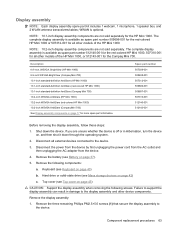
...on page 30). 5. Failure to support the display assembly can result in Hibernation, turn on automatically when high temperature conditions exist. Remove the battery (see Keyboard on page 33) b. NOTE: To properly ventilate the device, allow at least a 7.6-cm (3-inch)...and software requirements. Display assembly NOTE: Each display assembly spare part kit includes 1 microphone, 2 speakers, and 2 WLAN antenna transceivers/cables). Remove the following screws. Before removing the display assembly, follow these steps: 1. These conditions are unsure whether the device is designed ...
...on page 30). 5. Failure to support the display assembly can result in Hibernation, turn on automatically when high temperature conditions exist. Remove the battery (see Keyboard on page 33) b. NOTE: To properly ventilate the device, allow at least a 7.6-cm (3-inch)...and software requirements. Display assembly NOTE: Each display assembly spare part kit includes 1 microphone, 2 speakers, and 2 WLAN antenna transceivers/cables). Remove the following screws. Before removing the display assembly, follow these steps: 1. These conditions are unsure whether the device is designed ...

HP Mini 1000 NetBook - Maintenance and Service Guide
Page 58
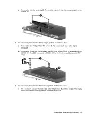
... is available using spare part number 506338-001. The speaker grill is necessary to replace the speakers, perform the following steps: a. b. Remove the two black Phillips PM2.0×8.0 screws (1) that secure the speaker assembly to release the pressure clips, and then remove the speaker grill. All display assembly subcomponent screws (for 8.9-inch panels only) are available...
... is available using spare part number 506338-001. The speaker grill is necessary to replace the speakers, perform the following steps: a. b. Remove the two black Phillips PM2.0×8.0 screws (1) that secure the speaker assembly to release the pressure clips, and then remove the speaker grill. All display assembly subcomponent screws (for 8.9-inch panels only) are available...

HP Mini 1000 NetBook - Maintenance and Service Guide
Page 59
The hinges (for 8.9-inch panels only) are available in the Display Hinge Kit, spare part number 504596-001. If it is available using spare part number 506335-001. 4. Component replacement procedures 51 Remove the speaker assembly (2). The speaker assembly is necessary to replace the display hinges, remove the two silver Phillips PM2.0×6.0 screws (1) that secure each hinge to the display enclosure, and then remove the hinges (2). c.
The hinges (for 8.9-inch panels only) are available in the Display Hinge Kit, spare part number 504596-001. If it is available using spare part number 506335-001. 4. Component replacement procedures 51 Remove the speaker assembly (2). The speaker assembly is necessary to replace the display hinges, remove the two silver Phillips PM2.0×6.0 screws (1) that secure each hinge to the display enclosure, and then remove the hinges (2). c.
HP Mini 1000 NetBook - Maintenance and Service Guide
Page 103
... spare part number 20, 21, 35 solid-state drives spare part number 13 speaker assembly illustrated 15 removal 50 spare part number 15, 20, 51 speaker grill illustrated 15 removal 50 spare part number 15, 20, 50 speakers 4 specifications device 60 display 61, 62 hard drive 63 I/O addresses 66 interrupts 65 memory map 68 solid...
... spare part number 20, 21, 35 solid-state drives spare part number 13 speaker assembly illustrated 15 removal 50 spare part number 15, 20, 51 speaker grill illustrated 15 removal 50 spare part number 15, 20, 50 speakers 4 specifications device 60 display 61, 62 hard drive 63 I/O addresses 66 interrupts 65 memory map 68 solid...
HP MINI User Guide - Windows XP
Page 8
...60 11 USB devices Using a USB device ...61 Connecting a USB device 61 Removing a USB device ...61 Using the HP Mini Mobile Drive Bay (select models only 62 Inserting the HP Mini Mobile Drive 62 Removing the HP Mini Mobile Drive 62 12 Pointing devices and keyboard Using pointing devices ...64 Setting pointing... brightness (fn+f3 67 Increasing screen brightness (fn+f4 67 Initiating QuickLock (fn+f6 67 Muting speaker sound (fn+f8 67 Decreasing speaker sound (fn+f10 67 Increasing speaker sound (fn+f11 67 13 Drives Handling drives ...68 Using external drives ...69 Using optional external ...
...60 11 USB devices Using a USB device ...61 Connecting a USB device 61 Removing a USB device ...61 Using the HP Mini Mobile Drive Bay (select models only 62 Inserting the HP Mini Mobile Drive 62 Removing the HP Mini Mobile Drive 62 12 Pointing devices and keyboard Using pointing devices ...64 Setting pointing... brightness (fn+f3 67 Increasing screen brightness (fn+f4 67 Initiating QuickLock (fn+f6 67 Muting speaker sound (fn+f8 67 Decreasing speaker sound (fn+f10 67 Increasing speaker sound (fn+f11 67 13 Drives Handling drives ...68 Using external drives ...69 Using optional external ...

HP MINI User Guide - Windows XP
Page 62
... then click Remove Favorite. To reduce the risk of personal injury, adjust the volume before putting on your device, follow these steps: 1. To connect external devices such as Screen Saver. To set as a screen saver, and then click Set as external speakers, headphones, or a microphone, refer... to set the photo favorite as a screen saver slide show. Removing your photo favorites To delete a photo favorite from the list, and click the Play button ...
... then click Remove Favorite. To reduce the risk of personal injury, adjust the volume before putting on your device, follow these steps: 1. To connect external devices such as Screen Saver. To set as a screen saver, and then click Set as external speakers, headphones, or a microphone, refer... to set the photo favorite as a screen saver slide show. Removing your photo favorites To delete a photo favorite from the list, and click the Play button ...
HP MINI User Guide - Windows XP
Page 96
... screen brightness 67 increasing speaker volume 67 initiating QuickLock 67 initiating Suspend 66 muting speaker sound 67 switching screen image 66 using 66 HP MediaStyle 15, 46 HP MIE Restore Image Creator identifying 79 using 80 HP Mini Mobile Drive inserting 62 removing 62 HP Mini Mobile Drive Bay identifying ...Mail section 26 media programs 15 memory module inserting 71 removing 71 memory module compartment cover release latch 70 removing 71 replacing 72 memory module compartment, identifying 10 microphone (audio-in) jack 8, 44 mini player next/fast forward button 48 pause button 48 play...
... screen brightness 67 increasing speaker volume 67 initiating QuickLock 67 initiating Suspend 66 muting speaker sound 67 switching screen image 66 using 66 HP MediaStyle 15, 46 HP MIE Restore Image Creator identifying 79 using 80 HP Mini Mobile Drive inserting 62 removing 62 HP Mini Mobile Drive Bay identifying ...Mail section 26 media programs 15 memory module inserting 71 removing 71 memory module compartment cover release latch 70 removing 71 replacing 72 memory module compartment, identifying 10 microphone (audio-in) jack 8, 44 mini player next/fast forward button 48 pause button 48 play...
HP MINI User Guide - Windows XP
Page 97
...multimedia components, identifying 43 music creating playlists 48 downloading 47 mini player 47 playing 47 music favorites changing 48 create new ...50 changing photo favorites 51 customizing photo favorites 51 downloading 50 removing photo favorites 52 setting as screen saver 52 viewing 51 ... release latches battery 10, 37 memory module compartment cover 70 restoring HP MIE Restore Image Creator 80 System Restore 79 right TouchPad button, identifying...down 42 Skype 15 software updates, installing 76 software, installing 18 speakers, identifying 9, 44 start new program, launching 13 storing battery ...
...multimedia components, identifying 43 music creating playlists 48 downloading 47 mini player 47 playing 47 music favorites changing 48 create new ...50 changing photo favorites 51 customizing photo favorites 51 downloading 50 removing photo favorites 52 setting as screen saver 52 viewing 51 ... release latches battery 10, 37 memory module compartment cover 70 restoring HP MIE Restore Image Creator 80 System Restore 79 right TouchPad button, identifying...down 42 Skype 15 software updates, installing 76 software, installing 18 speakers, identifying 9, 44 start new program, launching 13 storing battery ...

MINI User Guide - Windows XP
Page 84
...screen brightness 54 decreasing speaker sound 55 description 52 increasing screen brightness 54 increasing speaker volume 55 initiating QuickLock 54 initiating Standby 53 muting speaker sound 55 switching screen image 54 using 53 HP Mini Mobile Drive inserting 50 removing 50 stopping 50 HP Mobile Drive identifying ...Main menu 71 managing a power-on password 42 managing an administrator password 41 memory module inserting 59 removing 59 memory module compartment cover release latch 58 removing 59 replacing 60 memory module compartment, identifying 7 memory test 72 microphone (audio-in) jack 6, 33...
...screen brightness 54 decreasing speaker sound 55 description 52 increasing screen brightness 54 increasing speaker volume 55 initiating QuickLock 54 initiating Standby 53 muting speaker sound 55 switching screen image 54 using 53 HP Mini Mobile Drive inserting 50 removing 50 stopping 50 HP Mobile Drive identifying ...Main menu 71 managing a power-on password 42 managing an administrator password 41 memory module inserting 59 removing 59 memory module compartment cover release latch 58 removing 59 replacing 60 memory module compartment, identifying 7 memory test 72 microphone (audio-in) jack 6, 33...

MINI User Guide - Windows XP
Page 85
...of WLAN 27 Setup Utility, passwords set in 40 setup, device 1 shut down 22 software installing 35 multimedia 35 Windows Media Player 35 speakers, identifying 6, 33 Standby exiting 11 initiating 11 Standby hotkey 53 storing battery 21 switches power 4 wireless 4 System Configuration menu 71 system ...the device wireless certification labels 10 turning off the device 22 U unresponsive system 22 USB cable, connecting 48 USB devices connecting 48 description 48 removing 49 stopping 49 USB hubs 48 USB ports, identifying 5, 48 V vents, identifying 5, 6, 7 video transmission types 54 volume down hotkey,...
...of WLAN 27 Setup Utility, passwords set in 40 setup, device 1 shut down 22 software installing 35 multimedia 35 Windows Media Player 35 speakers, identifying 6, 33 Standby exiting 11 initiating 11 Standby hotkey 53 storing battery 21 switches power 4 wireless 4 System Configuration menu 71 system ...the device wireless certification labels 10 turning off the device 22 U unresponsive system 22 USB cable, connecting 48 USB devices connecting 48 description 48 removing 49 stopping 49 USB hubs 48 USB ports, identifying 5, 48 V vents, identifying 5, 6, 7 video transmission types 54 volume down hotkey,...


