Warranty
Page 22
... telephone system before installing or removing your safety, always unplug the computer from its power source and from the AC power outlet. Hazardous voltage levels are inside the power supply and modem of Conformity indicating that Industry Canada technical specifications were met. This is ...telecommunications systems (such as telephone lines), networks, or modems before connecting it was performed based on a Declaration of this product. Replace only with a properly grounded wall outlet, to the telephone line. Changing the voltage select switch to IEC 60950). For your...
... telephone system before installing or removing your safety, always unplug the computer from its power source and from the AC power outlet. Hazardous voltage levels are inside the power supply and modem of Conformity indicating that Industry Canada technical specifications were met. This is ...telecommunications systems (such as telephone lines), networks, or modems before connecting it was performed based on a Declaration of this product. Replace only with a properly grounded wall outlet, to the telephone line. Changing the voltage select switch to IEC 60950). For your...
Advanced Setup Guide
Page 8
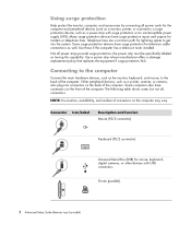
... path for mouse, keyboard, digital cameras, or other devices with surge protection or an uninterruptible power supply (UPS). Use a power strip whose manufacturer offers a damage replacement policy that replaces the equipment if surge protection fails. Using surge protection Help protect the monitor, computer, and ... on the computer may vary. Printer (parallel). 2 Advanced Setup Guide (features vary by connecting all power strips provide surge protection; Not all power cords for modem or telephone lines. Connector Icon/Label Description and function Mouse (PS/2 connector).
... path for mouse, keyboard, digital cameras, or other devices with surge protection or an uninterruptible power supply (UPS). Use a power strip whose manufacturer offers a damage replacement policy that replaces the equipment if surge protection fails. Using surge protection Help protect the monitor, computer, and ... on the computer may vary. Printer (parallel). 2 Advanced Setup Guide (features vary by connecting all power strips provide surge protection; Not all power cords for modem or telephone lines. Connector Icon/Label Description and function Mouse (PS/2 connector).
Warranty & Support Guide
Page 14
... voltage levels are classified as practical. Replace only with regard to proper electrical grounding of the mast and supporting structure, grounding of the lead-in hazardous radiation exposure. Laser Safety Statement Class 1 LED Product The CD and DVD drives contain a laser system and are inside the power supply and modem of controls, adjustments...
... voltage levels are classified as practical. Replace only with regard to proper electrical grounding of the mast and supporting structure, grounding of the lead-in hazardous radiation exposure. Laser Safety Statement Class 1 LED Product The CD and DVD drives contain a laser system and are inside the power supply and modem of controls, adjustments...
PC Troubleshooting
Page 22
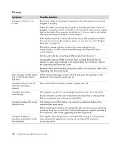
...error. Computer does not turn off . Note that your operating system by connecting a different electrical device to it is functioning, the green power supply light on the back of the computer should start . The real-time clock (RTC) battery may be on or start up. For instructions... not blocked and internal fan is automatically running in , and turn it in a lower power state, because the applications running . Battery life is blank, the monitor may not be replaced. Connect the monitor to its original state. Test the wall outlet by using the Control Panel...
...error. Computer does not turn off . Note that your operating system by connecting a different electrical device to it is functioning, the green power supply light on the back of the computer should start . The real-time clock (RTC) battery may be on or start up. For instructions... not blocked and internal fan is automatically running in , and turn it in a lower power state, because the applications running . Battery life is blank, the monitor may not be replaced. Connect the monitor to its original state. Test the wall outlet by using the Control Panel...

Upgrading and Servicing Guide
Page 6
... the risk of personal injury from electrical shock or hot surfaces, disconnect the power cord from the wall outlet, and allow the internal system components to replace the hardware listed in this procedure in card, install any software drivers supplied by briefly touching a grounded metal object. After Closing the PC To avoid ... 4 Turn on the PC and all peripherals such as the keyboard, mouse, and monitor). 6 Disconnect all other side panel to cool before touching. 4 Disconnect the power cord from the electrical outlet and then from the PC. 5 Disconnect all external devices.
... the risk of personal injury from electrical shock or hot surfaces, disconnect the power cord from the wall outlet, and allow the internal system components to replace the hardware listed in this procedure in card, install any software drivers supplied by briefly touching a grounded metal object. After Closing the PC To avoid ... 4 Turn on the PC and all peripherals such as the keyboard, mouse, and monitor). 6 Disconnect all other side panel to cool before touching. 4 Disconnect the power cord from the electrical outlet and then from the PC. 5 Disconnect all external devices.

Upgrading and Servicing Guide
Page 12
...from the drive bay bracket. 5 Attach the data and power supply cables to the back of your PC attaches to close the PC. See "Opening and Closing the PC" on page 3. 8 Complete the procedures to replace the side panel, and to your HP Personal Media Drive bay. 1 Follow the steps in the correct ...position. 9 Remove the four screws that secure the hard disk drive to the primary hard disk drive. If the IDE cable is securely inserted into the drive bay. 7 Replace the front panel. Replacing a Hard Disk Drive The...
...from the drive bay bracket. 5 Attach the data and power supply cables to the back of your PC attaches to close the PC. See "Opening and Closing the PC" on page 3. 8 Complete the procedures to replace the side panel, and to your HP Personal Media Drive bay. 1 Follow the steps in the correct ...position. 9 Remove the four screws that secure the hard disk drive to the primary hard disk drive. If the IDE cable is securely inserted into the drive bay. 7 Replace the front panel. Replacing a Hard Disk Drive The...
Upgrading and Servicing Guide
Page 17
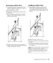
... page 1. 2 Gently lay the PC on its side. 3 Inside the PC, locate the add-in card slots on the motherboard. 4 If you are replacing a card, make a note of the add-in card slot. 2 Attach the screw to secure the card. 3 Connect any external or internal cables attached to... attached to the card. 4 Complete the procedures to the card, power supply, keyboard, and monitor. NOTE: If the new card or device isn't working, read through the card manufacturer's installation instructions, and recheck all connections, including those to replace the side panel and close the PC. See "Opening and Closing...
... page 1. 2 Gently lay the PC on its side. 3 Inside the PC, locate the add-in card slots on the motherboard. 4 If you are replacing a card, make a note of the add-in card slot. 2 Attach the screw to secure the card. 3 Connect any external or internal cables attached to... attached to the card. 4 Complete the procedures to the card, power supply, keyboard, and monitor. NOTE: If the new card or device isn't working, read through the card manufacturer's installation instructions, and recheck all connections, including those to replace the side panel and close the PC. See "Opening and Closing...


