
HP LaserJet Printer Family - Print Media Specification Guide
Page 52
...units 33 H heat, fuser operations of 2 temperature specifications 10 heavy paper HP 36 standard sizes 32 troubleshooting 23 using 7 high gloss laser paper, hp 36 hollow images, troubleshooting 28 HP color LaserJet printers bond paper, using 4..., avoiding 22 preprinted, using 6 information for 1 operations 2 HP LaserJet 2000 1 HP LaserJet 2686A 1 HP LaserJet 500 1 HP LaserJet Plus 1 HP LaserJet printers media designed for 1 operations 2 HP media, ordering 35 HP Monochrome LaserJet printers 1 HP Sales and Service Offices 2 HP website 2 humidity, storing media 19 I image quality, troubleshooting ...
...units 33 H heat, fuser operations of 2 temperature specifications 10 heavy paper HP 36 standard sizes 32 troubleshooting 23 using 7 high gloss laser paper, hp 36 hollow images, troubleshooting 28 HP color LaserJet printers bond paper, using 4..., avoiding 22 preprinted, using 6 information for 1 operations 2 HP LaserJet 2000 1 HP LaserJet 2686A 1 HP LaserJet 500 1 HP LaserJet Plus 1 HP LaserJet printers media designed for 1 operations 2 HP media, ordering 35 HP Monochrome LaserJet printers 1 HP Sales and Service Offices 2 HP website 2 humidity, storing media 19 I image quality, troubleshooting ...
Service Manual
Page 20
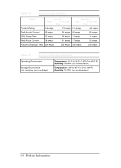
Table 1-6 Electrical Specifications Status 100/115 V 4/4M 4 Plus/4M Plus 220/240 V 4/4M 4 Plus/4M Plus Product Rating 6.4 amps 7.8 amps 3.1 amps 4.0 amps Peak Inrush Current 22 amps 22 amps 22 amps 22 amps 25% Decay Time 13 msec 18 msec 11 msec 11 msec Peak Fuser Current 38 amps 51 amps 17 amps 22 amps Return...
Table 1-6 Electrical Specifications Status 100/115 V 4/4M 4 Plus/4M Plus 220/240 V 4/4M 4 Plus/4M Plus Product Rating 6.4 amps 7.8 amps 3.1 amps 4.0 amps Peak Inrush Current 22 amps 22 amps 22 amps 22 amps 25% Decay Time 13 msec 18 msec 11 msec 11 msec Peak Fuser Current 38 amps 51 amps 17 amps 22 amps Return...

Service Manual
Page 118
...of paper, paper motion, and timing. (See Table 5-2.) Photosensor PS2 senses paper in the Fuser Assembly, and is empty. it detects the end of paper. PS5 terminates laser operation when ...paper in jam detection and registration. The condition of paper in jam detection. Note The LaserJet 5 printer uses different tray designators and associated messages as follows. The EMPTY message is only a... Cassette and the Envelope Feeder. PS1 detects paper at the Input Feed Roller and is empty; LJ 4 / 4 Plus MP Tray PC Tray LC Tray MP/PC/LC LOAD MP/PC/LC EMPTY LJ 5 Tray 1 Tray 2 Tray ...
...of paper, paper motion, and timing. (See Table 5-2.) Photosensor PS2 senses paper in the Fuser Assembly, and is empty. it detects the end of paper. PS5 terminates laser operation when ...paper in jam detection and registration. The condition of paper in jam detection. Note The LaserJet 5 printer uses different tray designators and associated messages as follows. The EMPTY message is only a... Cassette and the Envelope Feeder. PS1 detects paper at the Input Feed Roller and is empty; LJ 4 / 4 Plus MP Tray PC Tray LC Tray MP/PC/LC LOAD MP/PC/LC EMPTY LJ 5 Tray 1 Tray 2 Tray ...
Service Manual
Page 176
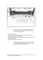
Allow plenty of time for the fuser to cool before beginning the fuser removal procedure. 1 Open the rear door. 2 Remove the (2) screws that hold the Fuser to the printer frame (see Figure 6-20, callout 1). 3 Slightly lift the Fuser by both the right and left sides to clear the locator points. 4 Pull the Fuser from the printer. Note The Fuser Assembly from the LaserJet 4 cannot be hot. Fuser Assembly Removal Figure 6-20 Caution Fuser Assembly Screws The Fuser Assembly may be interchanged with the Fuser Assembly from the LaserJet 4 Plus or 5 printers. 6-22 Removal and Replacement
Allow plenty of time for the fuser to cool before beginning the fuser removal procedure. 1 Open the rear door. 2 Remove the (2) screws that hold the Fuser to the printer frame (see Figure 6-20, callout 1). 3 Slightly lift the Fuser by both the right and left sides to clear the locator points. 4 Pull the Fuser from the printer. Note The Fuser Assembly from the LaserJet 4 cannot be hot. Fuser Assembly Removal Figure 6-20 Caution Fuser Assembly Screws The Fuser Assembly may be interchanged with the Fuser Assembly from the LaserJet 4 Plus or 5 printers. 6-22 Removal and Replacement
Service Manual
Page 203
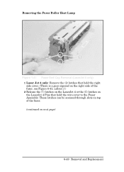
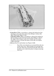
These latches can be accessed through slots on top of the fuser, see Figure 6-41, callout 1.) 2 Release the (7) latches on the LaserJet 4 or the (5) latches on next page) 6-49 Removal and Replacement Removing the Fuser Roller Heat Lamp Figure 1-41 Fuser End Cap Removal (LaserJet 4 only) 1 Laser Jet 4 only: Remove the (2) latches that hold the right side cover. (There is a gear exposed on the right side of the fuser. (continued on the LaserJet 4 Plus that hold the wire cover to the Fuser Assembly.
These latches can be accessed through slots on top of the fuser, see Figure 6-41, callout 1.) 2 Release the (7) latches on the LaserJet 4 or the (5) latches on next page) 6-49 Removal and Replacement Removing the Fuser Roller Heat Lamp Figure 1-41 Fuser End Cap Removal (LaserJet 4 only) 1 Laser Jet 4 only: Remove the (2) latches that hold the right side cover. (There is a gear exposed on the right side of the fuser. (continued on the LaserJet 4 Plus that hold the wire cover to the Fuser Assembly.
Service Manual
Page 204
These latches are accessed from the top of the wire cover. Figure 1-42 Fuser Wire Harness Cover Removal (LaserJet 4) 3 LaserJet 4: With a screwdriver, release the latches by first pressing to clear the lower latch, then lifting to release the upper latch. The slot on the side...end latches (see Figure 6-42a). Note Six of the wire harness cover is the best place to begin removing the cover. 6-50 Removal and Replacement LaserJet 4 Plus: With a screwdriver, release the latches by first pressing to clear the lower latch, then lifting to release the latch on the front left side ...
These latches are accessed from the top of the wire cover. Figure 1-42 Fuser Wire Harness Cover Removal (LaserJet 4) 3 LaserJet 4: With a screwdriver, release the latches by first pressing to clear the lower latch, then lifting to release the upper latch. The slot on the side...end latches (see Figure 6-42a). Note Six of the wire harness cover is the best place to begin removing the cover. 6-50 Removal and Replacement LaserJet 4 Plus: With a screwdriver, release the latches by first pressing to clear the lower latch, then lifting to release the latch on the front left side ...
Service Manual
Page 206
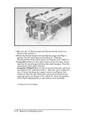
LaserJet 4 Plus/5: Remove the (2) screws from the end cover (see Figure 6-43, callout 3). 7 LaserJet 4: Remove the cable retainer from the fuser frame, and free the heat lamp lead from the cable retainer. Note the position of the cable retainer. Slide the Thermoswitch off the fuser frame (see Figure 6-43, callouts 4 and 5). Note the orientation of the...
LaserJet 4 Plus/5: Remove the (2) screws from the end cover (see Figure 6-43, callout 3). 7 LaserJet 4: Remove the cable retainer from the fuser frame, and free the heat lamp lead from the cable retainer. Note the position of the cable retainer. Slide the Thermoswitch off the fuser frame (see Figure 6-43, callouts 4 and 5). Note the orientation of the...
Service Manual
Page 209
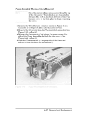
... the Wire Harness Cover as shown in Figure 6-42a (LaserJet 4) or Figure 6-42b and c (LaserJet 4 Plus). 2 Remove the (2) screws from the Thermoswitch connector (see Figure 6-46, callout 1). 3 Release the thermoswitch latch from the fuser frame (callout 3). Figure 1-46 Fuser Thermoswitch Connectors 6-55 Removal and Replacement Fuser Assembly Thermoswitch Removal Note Six of the seven latches are...
... the Wire Harness Cover as shown in Figure 6-42a (LaserJet 4) or Figure 6-42b and c (LaserJet 4 Plus). 2 Remove the (2) screws from the Thermoswitch connector (see Figure 6-46, callout 1). 3 Release the thermoswitch latch from the fuser frame (callout 3). Figure 1-46 Fuser Thermoswitch Connectors 6-55 Removal and Replacement Fuser Assembly Thermoswitch Removal Note Six of the seven latches are...
Service Manual
Page 212
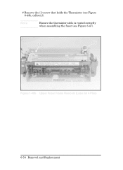
Note Ensure the thermistor cable is routed correctly when assembling the fuser (see Figure 6-48b, callout 2). 7 Remove the (1) screw that holds the Thermistor (see Figure 6-47). Figure 1-48b Upper Fuser Frame Removal (LaserJet 4 Plus) 6-58 Removal and Replacement
Note Ensure the thermistor cable is routed correctly when assembling the fuser (see Figure 6-48b, callout 2). 7 Remove the (1) screw that holds the Thermistor (see Figure 6-47). Figure 1-48b Upper Fuser Frame Removal (LaserJet 4 Plus) 6-58 Removal and Replacement
Service Manual
Page 251
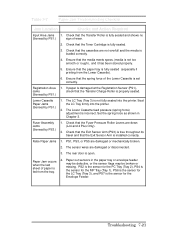
Registration Area Jams (Sensed by PS3.) 1. Seat the LC Tray firmly into the printer. Fuser Assembly Jams (Sensed by PS1.) 1. Paper out sensors in Chapter 3. Ensure that the media meets specs. (media is properly seated. If paper is damaged ...it has been stored properly. 5. False Paper Jams 1. Check that the Toner Cartridge is set correctly. The sensor wires are down (LJ4 and 4 Plus Only). 2. Check that the Fuser Pressure Roller Levers are damaged or disconnected. 3. Ensure that the Transfer Roller is fully seated and shows no (Sensed by PS1.) 1. PS1, PS3...
Registration Area Jams (Sensed by PS3.) 1. Seat the LC Tray firmly into the printer. Fuser Assembly Jams (Sensed by PS1.) 1. Paper out sensors in Chapter 3. Ensure that the media meets specs. (media is properly seated. If paper is damaged ...it has been stored properly. 5. False Paper Jams 1. Check that the Toner Cartridge is set correctly. The sensor wires are down (LJ4 and 4 Plus Only). 2. Check that the Fuser Pressure Roller Levers are damaged or disconnected. 3. Ensure that the Transfer Roller is fully seated and shows no (Sensed by PS1.) 1. PS1, PS3...
Service Manual
Page 260
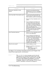
... room temperature. Replace the defective component (refer to room temperature. Does the error persist? 2. Remove the Fuser Assembly from the printer. Note The 50 SERVICE error message can be cleared immediately by shorting the C202 leads on the HP LaserJet 4/4M (or the C205 leads on the HP LaserJet 4 Plus/4M Plus/5/5M/5N) on the DC Controller.
... room temperature. Replace the defective component (refer to room temperature. Does the error persist? 2. Remove the Fuser Assembly from the printer. Note The 50 SERVICE error message can be cleared immediately by shorting the C202 leads on the HP LaserJet 4/4M (or the C205 leads on the HP LaserJet 4 Plus/4M Plus/5/5M/5N) on the DC Controller.


