

Service Manual
Page 9
... Removal 6-10 Multi-Purpose (MP) Tray (Tray 1) Door Removal . . . 6-12 Multi-Purpose (MP) Tray (Tray 1) Removal 6-13 Assemblies Removal 6-15 Power Supply Removal 6-15 Paper Feed Assembly Removal 6-18 High Voltage Power Supply (HVPS) Removal . . . . . 6-21 Fuser Assembly Removal 6-22 Control Panel and Overlay Removal 6-23 Removing the SIMMs Door 6-25 Formatter Cage Removal...
... Removal 6-10 Multi-Purpose (MP) Tray (Tray 1) Door Removal . . . 6-12 Multi-Purpose (MP) Tray (Tray 1) Removal 6-13 Assemblies Removal 6-15 Power Supply Removal 6-15 Paper Feed Assembly Removal 6-18 High Voltage Power Supply (HVPS) Removal . . . . . 6-21 Fuser Assembly Removal 6-22 Control Panel and Overlay Removal 6-23 Removing the SIMMs Door 6-25 Formatter Cage Removal...
Service Manual
Page 11
Drum Rotation Functional Check 7-50 High Voltage Power Supply Assembly 7-51 Interface Troubleshooting 7-52 Communications Check 7-52 Test Message 7-52 AUTOEXEC.BAT Standard Configurations . . . . . 7-53 Parallel DOS Commands 7-53 Serial ... Overview A-5 Installing the Optional Duplexer A-6 Removal and Replacement A-8 Required Tools A-8 Removing the Covers A-9 Removing the Switchback Covers A-9 Removing the Side Cover on Power Side A-10 Removing the Side Cover on Gear Side A-11 Removing the Back Cover A-13 Removing the Front Cover A-13 Removing Internal Duplexer Components A-14...
Drum Rotation Functional Check 7-50 High Voltage Power Supply Assembly 7-51 Interface Troubleshooting 7-52 Communications Check 7-52 Test Message 7-52 AUTOEXEC.BAT Standard Configurations . . . . . 7-53 Parallel DOS Commands 7-53 Serial ... Overview A-5 Installing the Optional Duplexer A-6 Removal and Replacement A-8 Required Tools A-8 Removing the Covers A-9 Removing the Switchback Covers A-9 Removing the Side Cover on Power Side A-10 Removing the Side Cover on Gear Side A-11 Removing the Back Cover A-13 Removing the Front Cover A-13 Removing Internal Duplexer Components A-14...
Service Manual
Page 114
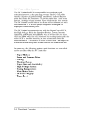
... Scanner Drive • Timing • Machine Status • Paper Size and Availability • High Voltage System • Fusing Temperature • Main Motor Drive • DC Power Supply • Toner Level 5-2 Functional Overview The amount of two serial data lines (SLI and SLO). The DC Controller also shares machine status information with paper...
... Scanner Drive • Timing • Machine Status • Paper Size and Availability • High Voltage System • Fusing Temperature • Main Motor Drive • DC Power Supply • Toner Level 5-2 Functional Overview The amount of two serial data lines (SLI and SLO). The DC Controller also shares machine status information with paper...
Service Manual
Page 143
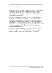
... be turned OFF for at least ten minutes. The high voltage power supply is provided to activate the AC power supply door switches before voltage is a discrete assembly located on the underside of the printer. The paper path doors must be closed to the heat lamp. Over-current protection... for use by a current monitoring circuit (crowbar circuit). The DC Controller PCA distributes voltages to the DC Power Supply and the fuser assembly heat lamp. ...
... be turned OFF for at least ten minutes. The high voltage power supply is provided to activate the AC power supply door switches before voltage is a discrete assembly located on the underside of the printer. The paper path doors must be closed to the heat lamp. Over-current protection... for use by a current monitoring circuit (crowbar circuit). The DC Controller PCA distributes voltages to the DC Power Supply and the fuser assembly heat lamp. ...

Service Manual
Page 169
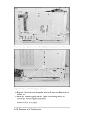
... socket (callout 4). b Remove the rod from the Rocker Switch at the lower right corner of the printer (see Figure 6-13a or b, callout 1.) Remove the metal cover. Assemblies Removal Power Supply Removal Figure 6-13a Remove the Sheet Metal Plate (LaserJet 4) 1 Remove the Right Side Cover. 2 Remove the (3) or (2) screws from the metal cover at the...
... socket (callout 4). b Remove the rod from the Rocker Switch at the lower right corner of the printer (see Figure 6-13a or b, callout 1.) Remove the metal cover. Assemblies Removal Power Supply Removal Figure 6-13a Remove the Sheet Metal Plate (LaserJet 4) 1 Remove the Right Side Cover. 2 Remove the (3) or (2) screws from the metal cover at the...
Service Manual
Page 170
Figure 6-13b Remove the Sheet Metal Plate (LaserJet 4 Plus/5) Figure 6-14 Power Supply Screws 4 Remove the (2) screws from the bottom frame (see Figure 6-14, callout 1). 5 Slide the power supply out the right side of the printer to access the power supply connectors. (continued on next page) 6-16 Removal and Replacement
Figure 6-13b Remove the Sheet Metal Plate (LaserJet 4 Plus/5) Figure 6-14 Power Supply Screws 4 Remove the (2) screws from the bottom frame (see Figure 6-14, callout 1). 5 Slide the power supply out the right side of the printer to access the power supply connectors. (continued on next page) 6-16 Removal and Replacement
Service Manual
Page 171
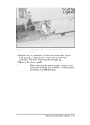
Note When replacing the power supply, be sure to use the screws with the star washers to ensure proper grounding and RFI shielding. Pull the 3-wire connector straight up. 7 Remove the power supply. Removal and Replacement 6-17 Figure 6-15 6-wire and 3-wire Connectors for the Power Supply 6 Remove the (2) connectors (6 wire and 3 wire). (See Figure 6-15, callout 1.) Squeeze the release tab on the 6-wire connector.
Note When replacing the power supply, be sure to use the screws with the star washers to ensure proper grounding and RFI shielding. Pull the 3-wire connector straight up. 7 Remove the power supply. Removal and Replacement 6-17 Figure 6-15 6-wire and 3-wire Connectors for the Power Supply 6 Remove the (2) connectors (6 wire and 3 wire). (See Figure 6-15, callout 1.) Squeeze the release tab on the 6-wire connector.

Service Manual
Page 175
...hold the PCA in place (see Figure 6-19, callout 1). 4 Release the (2) latches that hold the High Voltage Power Supply (see Figure 6-19, callout 2). 5 Pull the HVPS straight away from the printer to clear its locator pins and to prevent damage to align the high voltage connectors. If the...pages, the HVPS may be seated incorrectly. High Voltage Power Supply (HVPS) Removal Figure 6-19 HVPS Screws (2) and Latches (2) (Bottom View) 1 Remove the Toner Cartridge and PC tray. 2 Lay the printer on its left side. (Place a cloth under the printer to prevent marking the cover.) 3 Remove the (2) ...
...hold the PCA in place (see Figure 6-19, callout 1). 4 Release the (2) latches that hold the High Voltage Power Supply (see Figure 6-19, callout 2). 5 Pull the HVPS straight away from the printer to clear its locator pins and to prevent damage to align the high voltage connectors. If the...pages, the HVPS may be seated incorrectly. High Voltage Power Supply (HVPS) Removal Figure 6-19 HVPS Screws (2) and Latches (2) (Bottom View) 1 Remove the Toner Cartridge and PC tray. 2 Lay the printer on its left side. (Place a cloth under the printer to prevent marking the cover.) 3 Remove the (2) ...
Service Manual
Page 181
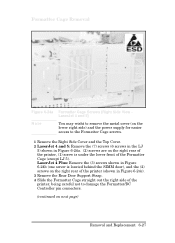
LaserJet 4 Plus: Remove the (3) screws shown in Figure 6-24b (one screw is located behind the SIMM door), and the (2) screws on the right rear of the printer (shown in Figure 6-24a. (2) screws are on the right rear of the printer, (1) screw is under the lower front of the printer, being ...careful not to damage the Formatter/DC Controller pin connectors. (continued on the lower right side) and the power supply for easier access to the Formatter Cage screws. 1 Remove the Right Side Cover and the Top Cover. 2 LaserJet 4 and 5: Remove the (7) ...
LaserJet 4 Plus: Remove the (3) screws shown in Figure 6-24b (one screw is located behind the SIMM door), and the (2) screws on the right rear of the printer (shown in Figure 6-24a. (2) screws are on the right rear of the printer, (1) screw is under the lower front of the printer, being ...careful not to damage the Formatter/DC Controller pin connectors. (continued on the lower right side) and the power supply for easier access to the Formatter Cage screws. 1 Remove the Right Side Cover and the Top Cover. 2 LaserJet 4 and 5: Remove the (7) ...
Service Manual
Page 187
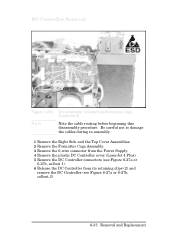
... re-assembly. 1 Remove the Right Side and the Top Cover Assemblies. 2 Remove the Formatter Cage Assembly. 3 Remove the 6-wire connector from the Power Supply. 4 Remove the plastic DC Controller cover (LaserJet 4 Plus). 5 Remove the DC Controller connectors (see Figure 6-27a or 6-27b, callout 1). 6 Release the DC Controller from its retaining clips (2) and remove the...
... re-assembly. 1 Remove the Right Side and the Top Cover Assemblies. 2 Remove the Formatter Cage Assembly. 3 Remove the 6-wire connector from the Power Supply. 4 Remove the plastic DC Controller cover (LaserJet 4 Plus). 5 Remove the DC Controller connectors (see Figure 6-27a or 6-27b, callout 1). 6 Release the DC Controller from its retaining clips (2) and remove the...
Service Manual
Page 223
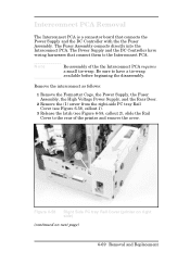
...rear of the the Interconnect PCA requires a small tie-wrap. Remove the interconnect as follows: 1 Remove the Formatter Cage, the Power Supply, the Fuser Assembly, the High Voltage Power Supply, and the Rear Door. 2 Remove the (1) screw from the right-side PC tray Rail Cover (see Figure 6-58, ... Assembly connects directly into the Interconnect PCA. Figure 6-58 Right Side PC tray Rail Cover (printer on right side) (continued on next page) 6-69 Removal and Replacement The Power Supply and the DC Controller have a tie-wrap available before beginning the disassembly. Note Re-assembly of...
...rear of the the Interconnect PCA requires a small tie-wrap. Remove the interconnect as follows: 1 Remove the Formatter Cage, the Power Supply, the Fuser Assembly, the High Voltage Power Supply, and the Rear Door. 2 Remove the (1) screw from the right-side PC tray Rail Cover (see Figure 6-58, ... Assembly connects directly into the Interconnect PCA. Figure 6-58 Right Side PC tray Rail Cover (printer on right side) (continued on next page) 6-69 Removal and Replacement The Power Supply and the DC Controller have a tie-wrap available before beginning the disassembly. Note Re-assembly of...
Service Manual
Page 242
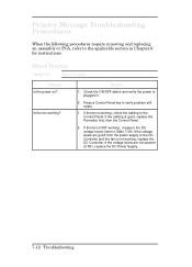
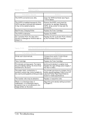
... Action 1. Press a Control Panel key to verify problem still exists. 1. Blank Display Table 7-3 Blank Display Checks Is the power on? Check the ON/OFF switch and verify the power is good, replace the Formatter first, then the Control Panel. 2. If the fan is working , measure the DC voltage ... NOT working , check the cabling to the Control Panel. If the voltage levels are good from the power supply to the DC Controller and the fan is not working ? Printer Message Troubleshooting Procedures When the following procedures require removing and replacing an assembly or PCA, refer to the...
... Action 1. Press a Control Panel key to verify problem still exists. 1. Blank Display Table 7-3 Blank Display Checks Is the power on? Check the ON/OFF switch and verify the power is good, replace the Formatter first, then the Control Panel. 2. If the fan is working , measure the DC voltage ... NOT working , check the cabling to the Control Panel. If the voltage levels are good from the power supply to the DC Controller and the fan is not working ? Printer Message Troubleshooting Procedures When the following procedures require removing and replacing an assembly or PCA, refer to the...
Service Manual
Page 255
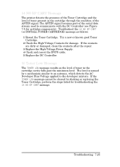
... the contacts after the repair. 3 Replace the High Voltage Power Supply. 4 Check and reseat the HVPS cable. 5 Replace the DC Controller. 16 Toner Low Message The TONER LOW message results as follows: 1 Reseat the Toner Cartridge. 14 NO EP CART Message The printer detects the presence of the Toner Cartridge and the level...
... the contacts after the repair. 3 Replace the High Voltage Power Supply. 4 Check and reseat the HVPS cable. 5 Replace the DC Controller. 16 Toner Low Message The TONER LOW message results as follows: 1 Reseat the Toner Cartridge. 14 NO EP CART Message The printer detects the presence of the Toner Cartridge and the level...
Service Manual
Page 259
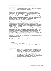
...mode, a temperature of the fusing system is NOT reached within 90 seconds after power-up. Troubleshooting 7-29 The purpose of approximately 172° C is maintained on the fuser roller. While the printer is in a fusing error: 1 Unable to maintain a temperature above approximately 180... above 230° C. 3 A condition wherein a temperature of the thermistor should be necessary to cool before turning the printer ON results in the AC Power Supply. The thermistor is HOT. A high intensity fusing lamp, located inside the fuser roller, provides the high temperature required for...
...mode, a temperature of the fusing system is NOT reached within 90 seconds after power-up. Troubleshooting 7-29 The purpose of approximately 172° C is maintained on the fuser roller. While the printer is in a fusing error: 1 Unable to maintain a temperature above approximately 180... above 230° C. 3 A condition wherein a temperature of the thermistor should be necessary to cool before turning the printer ON results in the AC Power Supply. The thermistor is HOT. A high intensity fusing lamp, located inside the fuser roller, provides the high temperature required for...
Service Manual
Page 260
... error message can be cleared immediately by shorting the C202 leads on the HP LaserJet 4/4M (or the C205 leads on the HP LaserJet 4 Plus/4M Plus/5/5M/5N) on the DC Controller. Remove the Fuser Assembly from the printer. Remove the Fuser Assembly and let it cool to clear (10 minutes)... printer ON. To check if one or the other is either the fusing bulb or the thermoswitch is correct. 2. It should read about 2 ohms (about 220 K ohms +/- 40 K ohms at ambient room temperature. If the thermistor is defective, perform the following components in the order given: Power Supply...
... error message can be cleared immediately by shorting the C202 leads on the HP LaserJet 4/4M (or the C205 leads on the HP LaserJet 4 Plus/4M Plus/5/5M/5N) on the DC Controller. Remove the Fuser Assembly from the printer. Remove the Fuser Assembly and let it cool to clear (10 minutes)... printer ON. To check if one or the other is either the fusing bulb or the thermoswitch is correct. 2. It should read about 2 ohms (about 220 K ohms +/- 40 K ohms at ambient room temperature. If the thermistor is defective, perform the following components in the order given: Power Supply...

Service Manual
Page 262
The sound can be heard, perform the following in the order given: 1 Check the Laser/Scanner and the Power Supply cables. Listen for the sound of the scanner motor when troubleshooting the 52 ERROR. 52 ERROR Scanner Malfunction The scanner motor is .... 3 Replace the DC Controller. 7-32 Troubleshooting Laser/Scanner Assembly Functional Checks Initiate a Self Test. The scanner motor is enabled when the printer is powered-up (during the printer's power-on self test), or whenever the PRINT command is received by the DC Controller. Motor operation is a flat, brushless, DC motor. The...
The sound can be heard, perform the following in the order given: 1 Check the Laser/Scanner and the Power Supply cables. Listen for the sound of the scanner motor when troubleshooting the 52 ERROR. 52 ERROR Scanner Malfunction The scanner motor is .... 3 Replace the DC Controller. 7-32 Troubleshooting Laser/Scanner Assembly Functional Checks Initiate a Self Test. The scanner motor is enabled when the printer is powered-up (during the printer's power-on self test), or whenever the PRINT command is received by the DC Controller. Motor operation is a flat, brushless, DC motor. The...
Service Manual
Page 268
... being certain to a darker level. Table 7-13 Any Faint Print Condition Possible Cause Action Printer set improperly. Replace the Toner Cartridge. Set the print density to fully seat the connectors....or no effect. Toner Cartridge. LaserJet Family Paper Specifications Guide for damage. Bad Primary Charging Roller. Change driver and/or Control Panel settings to the HP the electro-photographic printing process....transferred to Economode. Replace the high voltage power supply if this has no developer bias. Adjust the print density setting as shown in Chapter 3....
... being certain to a darker level. Table 7-13 Any Faint Print Condition Possible Cause Action Printer set improperly. Replace the Toner Cartridge. Set the print density to fully seat the connectors....or no effect. Toner Cartridge. LaserJet Family Paper Specifications Guide for damage. Bad Primary Charging Roller. Change driver and/or Control Panel settings to the HP the electro-photographic printing process....transferred to Economode. Replace the high voltage power supply if this has no developer bias. Adjust the print density setting as shown in Chapter 3....
Service Manual
Page 279
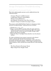
... the electro-photographic process are functioning, and troubleshoot the failure as follows: 1 Initiate an 05 SELF TEST. 2 Open or switch OFF the printer after the paper advances halfway through the printer (the leading edge of the Toner Image). • Transfer (Charge to transfer the image to view the drum's surface. If a dark... Half Self-Test Functional Check The electro-photographic process can be subdivided into the following pages. • The Drum Rotation Functional Check. • High voltage Power Supply Check.
... the electro-photographic process are functioning, and troubleshoot the failure as follows: 1 Initiate an 05 SELF TEST. 2 Open or switch OFF the printer after the paper advances halfway through the printer (the leading edge of the Toner Image). • Transfer (Charge to transfer the image to view the drum's surface. If a dark... Half Self-Test Functional Check The electro-photographic process can be subdivided into the following pages. • The Drum Rotation Functional Check. • High voltage Power Supply Check.
Service Manual
Page 281
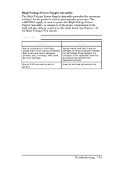
...Also check the Toner Cartridge. Clean the terminals with alcohol only. High Voltage Power Supply Assembly The High Voltage Power Supply Assembly provides the necessary voltages for the Primary Charge roller, Drum Ground, ...Developing Bias, Toner Level Sensor damaged, corroded, dirty, or missing? Table 7-29 High Voltage System Checks Checks Action Are the connectors for the printer's electro-photographic processes. If any are connected to power the High Voltage Power Supply...
...Also check the Toner Cartridge. Clean the terminals with alcohol only. High Voltage Power Supply Assembly The High Voltage Power Supply Assembly provides the necessary voltages for the Primary Charge roller, Drum Ground, ...Developing Bias, Toner Level Sensor damaged, corroded, dirty, or missing? Table 7-29 High Voltage System Checks Checks Action Are the connectors for the printer's electro-photographic processes. If any are connected to power the High Voltage Power Supply...
Service Manual
Page 290
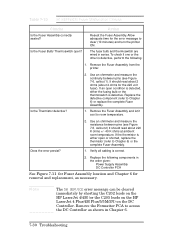
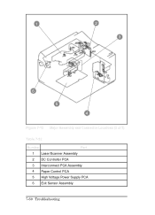
1 2 3 6 5 4 Figure 7-12 Major Assembly and Connector Locations (2 of 3) Table 7-32 Number Part 1 Laser/Scanner Assembly 2 DC Controller PCA 3 Interconnect PCA Assembly 4 Paper Control PCA 5 High Voltage Power Supply PCA 6 Exit Sensor Assembly 7-60 Troubleshooting
1 2 3 6 5 4 Figure 7-12 Major Assembly and Connector Locations (2 of 3) Table 7-32 Number Part 1 Laser/Scanner Assembly 2 DC Controller PCA 3 Interconnect PCA Assembly 4 Paper Control PCA 5 High Voltage Power Supply PCA 6 Exit Sensor Assembly 7-60 Troubleshooting

