User Manual
Page 6
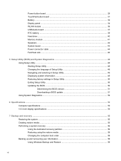
... Display panel ...34 WLAN module ...36 USB/Audio board ...37 RTC battery ...39 Hard drive ...40 Memory module ...41 Speakers ...42 System board ...43 Power connector cable ...44 Fan/Heat sink ...46 5 Setup Utility (BIOS) and... Utility ...50 Updating the BIOS ...50 Determining the BIOS version 51 Downloading a BIOS update 51 Using System Diagnostics ...52 6 Specifications ...53 Computer specifications ...53 13.3-inch display specifications ...53 7 Backup and recovery ...55 Restoring the system ...55 Creating restore media ...55 Performing a system recovery ...56 Using the dedicated recovery ...
... Display panel ...34 WLAN module ...36 USB/Audio board ...37 RTC battery ...39 Hard drive ...40 Memory module ...41 Speakers ...42 System board ...43 Power connector cable ...44 Fan/Heat sink ...46 5 Setup Utility (BIOS) and... Utility ...50 Updating the BIOS ...50 Determining the BIOS version 51 Downloading a BIOS update 51 Using System Diagnostics ...52 6 Specifications ...53 Computer specifications ...53 13.3-inch display specifications ...53 7 Backup and recovery ...55 Restoring the system ...55 Creating restore media ...55 Performing a system recovery ...56 Using the dedicated recovery ...
User Manual
Page 10
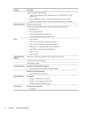
... 3012 Bluetooth 4.0 Combo Adapter ● Broadcom 4313GN 802.11b/g/n 1×1 WiFi and 20702 Bluetooth 4.0 Combo Adapter Push-pull insertion/removal HP Multi-Format Digital Media Reader supports the following digital card formats: ● MultiMediaCard ● Secure Digital (SD) Card ● Secure ...finish) TouchPad with multi-touch gestures Taps enabled as default Supports the following HP AC adapters: ● 65-W (non-smart) PFC RC V EM 3-wire HP AC adapter Supports the following batteries: ● 6-cell, 59 WHr 5.4 AH Li-ion battery Preinstalled: ● Windows 7 Home Basic (64-
... 3012 Bluetooth 4.0 Combo Adapter ● Broadcom 4313GN 802.11b/g/n 1×1 WiFi and 20702 Bluetooth 4.0 Combo Adapter Push-pull insertion/removal HP Multi-Format Digital Media Reader supports the following digital card formats: ● MultiMediaCard ● Secure Digital (SD) Card ● Secure ...finish) TouchPad with multi-touch gestures Taps enabled as default Supports the following HP AC adapters: ● 65-W (non-smart) PFC RC V EM 3-wire HP AC adapter Supports the following batteries: ● 6-cell, 59 WHr 5.4 AH Li-ion battery Preinstalled: ● Windows 7 Home Basic (64-
User Manual
Page 17
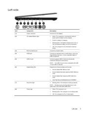
NOTE: The USB 3.0 port is not connected to external power. Left side Item (1) (2) Component Power connector AC adapter/Battery light (3) RJ-45 (network) jack (4) HDMI port (5) USB 3.0 port (6) Digital Media Slot (7) Hard drive light (8) Power light Description Connects...adapter. ● White: The computer is connected to external power and the battery is fully charged. ● Amber: A battery is charging. ● Blinking white: The battery charge level is 12% or less (recharge the battery as soon as a high-definition television, or any compatible digital or audio ...
NOTE: The USB 3.0 port is not connected to external power. Left side Item (1) (2) Component Power connector AC adapter/Battery light (3) RJ-45 (network) jack (4) HDMI port (5) USB 3.0 port (6) Digital Media Slot (7) Hard drive light (8) Power light Description Connects...adapter. ● White: The computer is connected to external power and the battery is fully charged. ● Amber: A battery is charging. ● Blinking white: The battery charge level is 12% or less (recharge the battery as soon as a high-definition television, or any compatible digital or audio ...
User Manual
Page 22
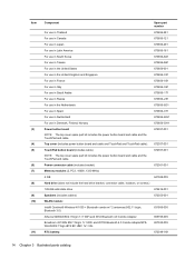
... 4.0 Combo Adapter 655795-005 Broadcom 4313GN 802.11b/g/n 1×1 WiFi and 20702 Bluetooth 4.0 Combo AdapterSPSWLAN 802.11bgn+BT4 BC HMC 1x1 VAL 657325-005 RTC battery: 672349-001 14 Chapter 3 Illustrated parts catalog
... 4.0 Combo Adapter 655795-005 Broadcom 4313GN 802.11b/g/n 1×1 WiFi and 20702 Bluetooth 4.0 Combo AdapterSPSWLAN 802.11bgn+BT4 BC HMC 1x1 VAL 657325-005 RTC battery: 672349-001 14 Chapter 3 Illustrated parts catalog
User Manual
Page 23
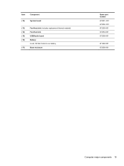
Item Component (12) System board (13) Fan-Heat sink (includes replacement thermal material) (14) Fan-Heat sink (15) USB/Audio board (16) Battery: 6-cell, 59 WHr 5.4AH Li-ion battery (17) Base enclosure Spare part number 672351-001 672352-001 672355-001 672354-001 672358-001 671602-001 672356-001 Computer major components 15
Item Component (12) System board (13) Fan-Heat sink (includes replacement thermal material) (14) Fan-Heat sink (15) USB/Audio board (16) Battery: 6-cell, 59 WHr 5.4AH Li-ion battery (17) Base enclosure Spare part number 672351-001 672352-001 672355-001 672354-001 672358-001 671602-001 672356-001 Computer major components 15
User Manual
Page 25
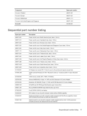
...-RW Super Multi Double-Layer Combo Drive Blu-ray ROM DVD±R/RW Super Multi Double-Layer Drive 6-cell, 59 WHr 5.4AH Li-ion battery RTC battery for use only with computer models without WWAN capability Display assembly for use with computer models equipped with WLAN only capability in black finish (includes...
...-RW Super Multi Double-Layer Combo Drive Blu-ray ROM DVD±R/RW Super Multi Double-Layer Drive 6-cell, 59 WHr 5.4AH Li-ion battery RTC battery for use only with computer models without WWAN capability Display assembly for use with computer models equipped with WLAN only capability in black finish (includes...
User Manual
Page 38
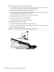
...Remove the base enclosure screws (see Top cover on page 25). 5. Remove the top cover (see Base enclosure on page 28). 7. Disconnect the battery cable (see Keyboard on page 32). Disconnect the power from the computer by first unplugging the power cord from the AC outlet and then unplugging... the AC adapter from the computer. 4. Before removing the Power button board, follow these steps: 1. Remove the keyboard (see Battery on page 26). 6. Turn the top cover upside down the computer. Remove the Power button board (2). Shut down , with the back edge toward...
...Remove the base enclosure screws (see Top cover on page 25). 5. Remove the top cover (see Base enclosure on page 28). 7. Disconnect the battery cable (see Keyboard on page 32). Disconnect the power from the computer by first unplugging the power cord from the AC outlet and then unplugging... the AC adapter from the computer. 4. Before removing the Power button board, follow these steps: 1. Remove the keyboard (see Battery on page 26). 6. Turn the top cover upside down the computer. Remove the Power button board (2). Shut down , with the back edge toward...
User Manual
Page 40
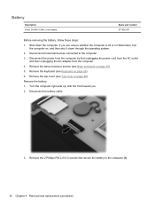
Remove the battery: 1. Disconnect the battery cable. 3. Shut down through the operating system. 2. Remove the keyboard (see Top cover on page 26). 6. Remove the top cover (see Keyboard on page 28). ... the power cord from the AC outlet and then unplugging the AC adapter from the computer. 4. Remove the 2 Phillips PM 2.0×3.0 screws that secure the battery to the computer. 3. Turn the computer right-side up, with the front toward you are unsure whether the computer is off or in Hibernation, turn...
Remove the battery: 1. Disconnect the battery cable. 3. Shut down through the operating system. 2. Remove the keyboard (see Top cover on page 26). 6. Remove the top cover (see Keyboard on page 28). ... the power cord from the AC outlet and then unplugging the AC adapter from the computer. 4. Remove the 2 Phillips PM 2.0×3.0 screws that secure the battery to the computer. 3. Turn the computer right-side up, with the front toward you are unsure whether the computer is off or in Hibernation, turn...
User Manual
Page 41
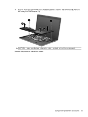
4. Support the display panel while lifting the battery slightly, and then slide it is not damaged. Component replacement procedures 33 CAUTION: Make sure that you balance the battery carefully so that it forward (2). Reverse this procedure to install the battery. Remove the battery from the computer (3).
4. Support the display panel while lifting the battery slightly, and then slide it is not damaged. Component replacement procedures 33 CAUTION: Make sure that you balance the battery carefully so that it forward (2). Reverse this procedure to install the battery. Remove the battery from the computer (3).
User Manual
Page 42
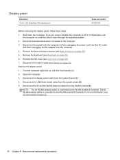
Remove the top cover (see Battery on page 28). 7. Disconnect the battery cable (see Top cover on page 32). Disconnect the #1 and #2 WLAN antenna cables from the system board (1). 4. NOTE: The #1 WLAN antenna cable is connected to the WLAN module #2 terminal. Display panel Description 13.3-in Hibernation, turn the computer on page 36, 34...
Remove the top cover (see Battery on page 28). 7. Disconnect the battery cable (see Top cover on page 32). Disconnect the #1 and #2 WLAN antenna cables from the system board (1). 4. NOTE: The #1 WLAN antenna cable is connected to the WLAN module #2 terminal. Display panel Description 13.3-in Hibernation, turn the computer on page 36, 34...
User Manual
Page 44
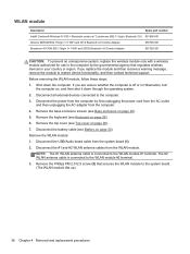
... first unplugging the power cord from the AC outlet and then unplugging the AC adapter from the system board (1). 2. Remove the keyboard (see Battery on page 26). 6. Disconnect the battery cable (see Keyboard on page 32). NOTE: The #1 WLAN antenna cable is connected to the WLAN module #2 terminal. 3. Disconnect all external devices...
... first unplugging the power cord from the AC outlet and then unplugging the AC adapter from the system board (1). 2. Remove the keyboard (see Battery on page 26). 6. Disconnect the battery cable (see Keyboard on page 32). NOTE: The #1 WLAN antenna cable is connected to the WLAN module #2 terminal. 3. Disconnect all external devices...
User Manual
Page 45
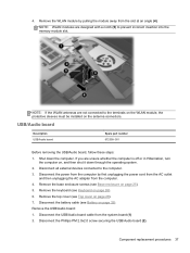
... computer is off or in Hibernation, turn the computer on the antenna connectors. Remove the USB/Audio board: 1. Remove the keyboard (see Battery on page 26). 6. Disconnect the battery cable (see Keyboard on page 32). USB/Audio board Description USB/Audio board Spare part number 672358-001 Before removing the USB/Audio...
... computer is off or in Hibernation, turn the computer on the antenna connectors. Remove the USB/Audio board: 1. Remove the keyboard (see Battery on page 26). 6. Disconnect the battery cable (see Keyboard on page 32). USB/Audio board Description USB/Audio board Spare part number 672358-001 Before removing the USB/Audio...
User Manual
Page 47
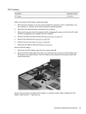
...cover (see Base enclosure on page 28). 7. Component replacement procedures 39 Disconnect all external devices connected to install the RTC battery on page 32). Remove the base enclosure screws (see Top cover on page 25). 5. Disconnect the power from the ...the AC adapter from the system board (1). 2. Remove the RTC battery (2). RTC battery Description RTC battery Spare part number 672349-001 Before removing the RTC battery, follow these steps: 1. Remove the RTC battery: 1. Disconnect the RTC battery cable from the computer. 4. Shut down through the operating system...
...cover (see Base enclosure on page 28). 7. Component replacement procedures 39 Disconnect all external devices connected to install the RTC battery on page 32). Remove the base enclosure screws (see Top cover on page 25). 5. Disconnect the power from the ...the AC adapter from the system board (1). 2. Remove the RTC battery (2). RTC battery Description RTC battery Spare part number 672349-001 Before removing the RTC battery, follow these steps: 1. Remove the RTC battery: 1. Disconnect the RTC battery cable from the computer. 4. Shut down through the operating system...
User Manual
Page 48
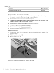
...base enclosure screws (see Keyboard on page 26). 6. Remove the keyboard (see Base enclosure on page 28). 7. Remove the hard drive (3). Disconnect the battery cable (see Top cover on page 25). 5. Pull the hard drive to reassemble and install the hard drive. 40 Chapter 4 Removal and replacement procedures..., turn the computer on page 32). Shut down through the operating system. 2. Remove the hard drive: 1. Remove the top cover (see Battery on , and then shut it down the computer. Hard drive Description 128-GB mSATA solid-state drive (SSD) Spare part number 672616-001 ...
...base enclosure screws (see Keyboard on page 26). 6. Remove the keyboard (see Base enclosure on page 28). 7. Remove the hard drive (3). Disconnect the battery cable (see Top cover on page 25). 5. Pull the hard drive to reassemble and install the hard drive. 40 Chapter 4 Removal and replacement procedures..., turn the computer on page 32). Shut down through the operating system. 2. Remove the hard drive: 1. Remove the top cover (see Battery on , and then shut it down the computer. Hard drive Description 128-GB mSATA solid-state drive (SSD) Spare part number 672616-001 ...
User Manual
Page 49
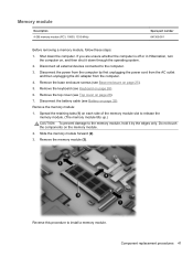
... the computer by the edges only. Slide the memory module forward (2). 3. Disconnect the power from the computer. 4. Remove the base enclosure screws (see Battery on page 25). 5. Disconnect the battery cable (see Base enclosure on page 32). Remove the memory module: 1. Reverse this procedure to the computer. 3. Spread the retaining tabs (1) on...
... the computer by the edges only. Slide the memory module forward (2). 3. Disconnect the power from the computer. 4. Remove the base enclosure screws (see Battery on page 25). 5. Disconnect the battery cable (see Base enclosure on page 32). Remove the memory module: 1. Reverse this procedure to the computer. 3. Spread the retaining tabs (1) on...
User Manual
Page 50
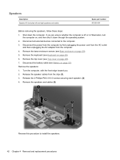
... or in Hibernation, turn the computer on, and then shut it down the computer. Release the 2 Phillips PM 2.0×3.0 screws securing each speaker. (2) 4. Disconnect the battery cable (see Top cover on page 32). Remove the speakers: 1. Release the speaker cables from the computer. 4. Shut down through the operating system. 2. Disconnect all...
... or in Hibernation, turn the computer on, and then shut it down the computer. Release the 2 Phillips PM 2.0×3.0 screws securing each speaker. (2) 4. Disconnect the battery cable (see Top cover on page 32). Remove the speakers: 1. Release the speaker cables from the computer. 4. Shut down through the operating system. 2. Disconnect all...
User Manual
Page 51
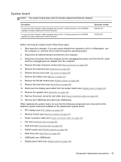
... cover (see Power connector cable on page 42). 12. Disconnect the display panel cable from the system board (see Speakers on page 44). 13. Remove the speaker (see Display panel on page 34). System board NOTE: The system board spare part kit includes replacement thermal material. Shut...from the AC outlet and then unplugging the AC adapter from the defective system board and installed on the replacement system board: ● RTC battery (see RTC battery on page 39) ● Memory module (see Memory module on page 41) ● Power connector cable (see Power connector cable on ...
... cover (see Power connector cable on page 42). 12. Disconnect the display panel cable from the system board (see Speakers on page 44). 13. Remove the speaker (see Display panel on page 34). System board NOTE: The system board spare part kit includes replacement thermal material. Shut...from the AC outlet and then unplugging the AC adapter from the defective system board and installed on the replacement system board: ● RTC battery (see RTC battery on page 39) ● Memory module (see Memory module on page 41) ● Power connector cable (see Power connector cable on ...
User Manual
Page 53
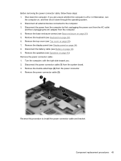
... power from the computer by first unplugging the power cord from the AC outlet and then unplugging the AC adapter from the computer. 4. Disconnect the battery cable (see Base enclosure on page 25). 5. Before removing the power connector cable, follow these steps: 1. Remove the base enclosure screws (see...
... power from the computer by first unplugging the power cord from the AC outlet and then unplugging the AC adapter from the computer. 4. Disconnect the battery cable (see Base enclosure on page 25). 5. Before removing the power connector cable, follow these steps: 1. Remove the base enclosure screws (see...
User Manual
Page 54
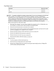
...properly ventilate the computer, allow at least 7.6 cm (3 in Hibernation, turn on automatically when high temperature conditions exist. Remove the keyboard (see Battery on page 32), Remove the fan: 1. Disconnect all external devices connected to turn the computer on the left side of the computer. Remove ... from the system board. 3. Shut down through the ventilation grill located on , and then shut it down the computer. Disconnect the battery cable (see Keyboard on the left side of the computer. These conditions are unsure whether the computer is off or in ) of ...
...properly ventilate the computer, allow at least 7.6 cm (3 in Hibernation, turn on automatically when high temperature conditions exist. Remove the keyboard (see Battery on page 32), Remove the fan: 1. Disconnect all external devices connected to turn the computer on the left side of the computer. Remove ... from the system board. 3. Shut down through the ventilation grill located on , and then shut it down the computer. Disconnect the battery cable (see Keyboard on the left side of the computer. These conditions are unsure whether the computer is off or in ) of ...
User Manual
Page 59
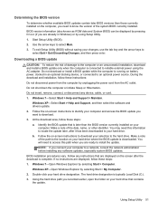
... AC adapter. Make a note of damage to the computer or an unsuccessful installation, download and install a BIOS update only when the computer is running on battery power, docked in Windows) or by unplugging the power cord from the AC outlet. The hard drive designation is downloaded. Do not download or install...
... AC adapter. Make a note of damage to the computer or an unsuccessful installation, download and install a BIOS update only when the computer is running on battery power, docked in Windows) or by unplugging the power cord from the AC outlet. The hard drive designation is downloaded. Do not download or install...


