
Hardware Reference Guide - dx2400 MT
Page 5
Table of contents 1 Product Features Standard Configuration Features ...1 Front Panel Components ...2 Media Card Reader Components ...3 Rear Panel Components ...4 Keyboard ...5 Using the Windows Logo Key 6 Serial Number Location ...7 2 Hardware Upgrades Warnings and Cautions ...8 Removing ... Additional Memory ...14 DIMMs ...14 DDR2-SDRAM DIMMs ...14 Populating DIMM Sockets 15 Installing DIMMs ...16 Removing or Installing an Expansion Card 18 Drive Positions ...23 Installing Additional Drives ...24 System Board Drive Connections 26 Removing an Optical Drive 27 Installing an Optical Drive ...
Table of contents 1 Product Features Standard Configuration Features ...1 Front Panel Components ...2 Media Card Reader Components ...3 Rear Panel Components ...4 Keyboard ...5 Using the Windows Logo Key 6 Serial Number Location ...7 2 Hardware Upgrades Warnings and Cautions ...8 Removing ... Additional Memory ...14 DIMMs ...14 DDR2-SDRAM DIMMs ...14 Populating DIMM Sockets 15 Installing DIMMs ...16 Removing or Installing an Expansion Card 18 Drive Positions ...23 Installing Additional Drives ...24 System Board Drive Connections 26 Removing an Optical Drive 27 Installing an Optical Drive ...

Hardware Reference Guide - dx2400 MT
Page 8
An optional diskette drive is available from HP for this drive bay. 2 Chapter 1 Product Features ENWW Figure 1-2 Front Panel Components Table 1-1 Front Panel Components 1 5.25-inch Optical Drives1 6 Hard Drive Activity Light 2 Optical Drive Activity Lights 7 Optical Drive Eject Buttons 3 3.5-inch Media Card Reader (optional)2 8 Headphone Connector 4 Microphone Connector 9 USB (Universal Serial Bus) 2.0 Ports...
An optional diskette drive is available from HP for this drive bay. 2 Chapter 1 Product Features ENWW Figure 1-2 Front Panel Components Table 1-1 Front Panel Components 1 5.25-inch Optical Drives1 6 Hard Drive Activity Light 2 Optical Drive Activity Lights 7 Optical Drive Eject Buttons 3 3.5-inch Media Card Reader (optional)2 8 Headphone Connector 4 Microphone Connector 9 USB (Universal Serial Bus) 2.0 Ports...

Hardware Reference Guide - dx2400 MT
Page 9
Figure 1-3 Media Card Reader Components Table 1-2 Media Card Reader Components 1 SmartMedia/xD ● 3.3V SmartMedia Card (SM) ● D-Picture Card (xD) 2 Media Card Reader Activity Light 3 SD/MMC+/miniSD ● Secure Digital Card (SD) ● MiniSD ● MultiMediaCard (MMC) ● Reduced Size MultiMediaCard (RS MMC)...Memory Stick PRO Duo (MS PRO Duo) ENWW Media Card Reader Components 3 Refer to the following illustration and table to identify the media card reader components. Media Card Reader Components The media card reader is an optional device available on some models only....
Figure 1-3 Media Card Reader Components Table 1-2 Media Card Reader Components 1 SmartMedia/xD ● 3.3V SmartMedia Card (SM) ● D-Picture Card (xD) 2 Media Card Reader Activity Light 3 SD/MMC+/miniSD ● Secure Digital Card (SD) ● MiniSD ● MultiMediaCard (MMC) ● Reduced Size MultiMediaCard (RS MMC)...Memory Stick PRO Duo (MS PRO Duo) ENWW Media Card Reader Components 3 Refer to the following illustration and table to identify the media card reader components. Media Card Reader Components The media card reader is an optional device available on some models only....

Hardware Reference Guide - dx2400 MT
Page 29
... Figure 2-15 Drive Positions 1 Two 5.25-inch external drive bays for optional drives (optical drives shown) 2 One 3.5-inch external drive bay for optional drive (media card reader shown) 3 Primary 3.5-inch internal hard drive bay 4 Secondary 3.5-inch internal hard drive bay for more information. Reconfigure the computer, if necessary. Refer to the Computer...
... Figure 2-15 Drive Positions 1 Two 5.25-inch external drive bays for optional drives (optical drives shown) 2 One 3.5-inch external drive bay for optional drive (media card reader shown) 3 Primary 3.5-inch internal hard drive bay 4 Secondary 3.5-inch internal hard drive bay for more information. Reconfigure the computer, if necessary. Refer to the Computer...

Hardware Reference Guide - dx2400 MT
Page 30
... board in the following order: SATA0, SATA1, SATA3, SATA2. ● Connect a diskette drive to the connector labeled FLOPPY. ● Connect a media card reader to the USB connector labeled F_USB2. ● The system does not support Parallel ATA (PATA) optical drives or PATA hard drives. ● You may ...a third-height or a half-height drive into a half-height bay. ● If needed, HP has provided extra drive retainer screws on the interior of the front bezel that are silver. The HP-supplied M3 metric guide screws (1) are black. All other drives use 6-32 standard screws. Hard drives...
... board in the following order: SATA0, SATA1, SATA3, SATA2. ● Connect a diskette drive to the connector labeled FLOPPY. ● Connect a media card reader to the USB connector labeled F_USB2. ● The system does not support Parallel ATA (PATA) optical drives or PATA hard drives. ● You may ...a third-height or a half-height drive into a half-height bay. ● If needed, HP has provided extra drive retainer screws on the interior of the front bezel that are silver. The HP-supplied M3 metric guide screws (1) are black. All other drives use 6-32 standard screws. Hard drives...

Hardware Reference Guide - dx2400 MT
Page 32
System Board Connector System Board Label 1 Media Card Reader F_USB2 2 SATA0 SATA0 3 SATA1 SATA1 4 SATA2 SATA2 5 SATA3 SATA3 6 Diskette Drive FLOPPY Color black dark blue white light blue orange black 26 Chapter 2 Hardware Upgrades ENWW System Board Drive Connections Refer to the following illustration and table to identify the system board drive connectors. Figure 2-17 System Board Drive Connections Table 2-3 System Board Drive Connections No.
System Board Connector System Board Label 1 Media Card Reader F_USB2 2 SATA0 SATA0 3 SATA1 SATA1 4 SATA2 SATA2 5 SATA3 SATA3 6 Diskette Drive FLOPPY Color black dark blue white light blue orange black 26 Chapter 2 Hardware Upgrades ENWW System Board Drive Connections Refer to the following illustration and table to identify the system board drive connectors. Figure 2-17 System Board Drive Connections Table 2-3 System Board Drive Connections No.

Hardware Reference Guide - dx2400 MT
Page 36
... SATA1 . Lock any security devices that were disengaged when the access panel was removed. NOTE: The 3.5-inch drive bay may contain a diskette drive or a media card reader. 1. Turn off any external devices. CAUTION: Regardless of a drive before removing the drive from the computer. 10. If the system configuration includes only one optical...
... SATA1 . Lock any security devices that were disengaged when the access panel was removed. NOTE: The 3.5-inch drive bay may contain a diskette drive or a media card reader. 1. Turn off any external devices. CAUTION: Regardless of a drive before removing the drive from the computer. 10. If the system configuration includes only one optical...

Hardware Reference Guide - dx2400 MT
Page 37
If you are removing a diskette drive, disconnect the data cable (1) and power cable (2) from the system board. Figure 2-22 Disconnecting the Diskette Drive Cables b. Figure 2-23 Disconnecting the Media Card Reader Cable ENWW Installing Additional Drives 31 6. Disconnect the drive cables, as indicated in the following illustrations: a. If you are removing a media card reader, disconnect the USB cable from the back of the drive.
If you are removing a diskette drive, disconnect the data cable (1) and power cable (2) from the system board. Figure 2-22 Disconnecting the Diskette Drive Cables b. Figure 2-23 Disconnecting the Media Card Reader Cable ENWW Installing Additional Drives 31 6. Disconnect the drive cables, as indicated in the following illustrations: a. If you are removing a media card reader, disconnect the USB cable from the back of the drive.

Hardware Reference Guide - dx2400 MT
Page 38
.... If you are adding a drive to the bay (1) then slide the drive forward and out of the computer can be configured with a media card reader or a diskette drive. 1. Disconnect the power cord from the power outlet and disconnect any security devices that secures the drive to an empty drive...Discard the knockout plate. 8. If the new drive has screws installed on page 12 for the first time, you are installing a diskette drive or media card reader in a bay covered by a bezel blank, remove the front bezel then remove the bezel blank. Remove the access panel and front bezel. 6. See ...
.... If you are adding a drive to the bay (1) then slide the drive forward and out of the computer can be configured with a media card reader or a diskette drive. 1. Disconnect the power cord from the power outlet and disconnect any security devices that secures the drive to an empty drive...Discard the knockout plate. 8. If the new drive has screws installed on page 12 for the first time, you are installing a diskette drive or media card reader in a bay covered by a bezel blank, remove the front bezel then remove the bezel blank. Remove the access panel and front bezel. 6. See ...

Hardware Reference Guide - dx2400 MT
Page 39
...Replace the front bezel and access panel. 12. NOTE: Extra drive retainer screws are black. If installing a media card reader, connect the USB cable from the media card reader to Installing Additional Drives on the interior of the front bezel if needed. b. Reconnect the power cord and turn ...labeled F_USB2. The M3 metric retainer screws for diskette drives or media card readers are provided on page 24 for an illustration of the retainer screws location. Figure 2-25 Installing a 3.5-inch Device (Media Card Reader Shown) 10. Slide the drive in through the front of the data...
...Replace the front bezel and access panel. 12. NOTE: Extra drive retainer screws are black. If installing a media card reader, connect the USB cable from the media card reader to Installing Additional Drives on the interior of the front bezel if needed. b. Reconnect the power cord and turn ...labeled F_USB2. The M3 metric retainer screws for diskette drives or media card readers are provided on page 24 for an illustration of the retainer screws location. Figure 2-25 Installing a 3.5-inch Device (Media Card Reader Shown) 10. Slide the drive in through the front of the data...
Hardware Reference Guide - dx2400 MT
Page 58
... memory 14 optical drive 29 security locks 45 K keyboard components 5 connector 4 L line-in connector 4 line-out connector 4 locks cable lock 45 HP Business PC Security Lock 46 padlock 46 52 Index M media card reader features 3 installing 32 removing 30 memory installing 14 populating sockets 15 specifications 14 microphone connector 2, 4 monitor, connecting 4 mouse connector 4 N network...
... memory 14 optical drive 29 security locks 45 K keyboard components 5 connector 4 L line-in connector 4 line-out connector 4 locks cable lock 45 HP Business PC Security Lock 46 padlock 46 52 Index M media card reader features 3 installing 32 removing 30 memory installing 14 populating sockets 15 specifications 14 microphone connector 2, 4 monitor, connecting 4 mouse connector 4 N network...
HP Compaq dx2400 Microtower Business PC: Illustrated Parts & Service Map
Page 2
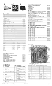
..., Agere 2006 PCI Hi-Speed, FH 398661-001 nVidia GeForce 8400 GS 256-MB video card with DMS-59 and TV (S-Video) outputs, LP 445743-001 DVI, SDVO graphics card, FH 398333-001 HP FireWire IEEE 1394 PCI card, 2 external, 1 internal port, FH 441448-001 Intel Pro 1000 PT Gigabit PCIe NIC, FH ... drive connectors DIMM 1 DIMM 4 Memory slots AUDIO Double stack audio connector PROCESSOR Processor socket ATXPOWER Main power F_USB1 Front USB FLOPPY Diskette drive F_USB2 Media card reader F_AUDIO Front audio ATX_CPU CPU power dx2400 Illustrated Parts & Service Map 484985-001 page 2
..., Agere 2006 PCI Hi-Speed, FH 398661-001 nVidia GeForce 8400 GS 256-MB video card with DMS-59 and TV (S-Video) outputs, LP 445743-001 DVI, SDVO graphics card, FH 398333-001 HP FireWire IEEE 1394 PCI card, 2 external, 1 internal port, FH 441448-001 Intel Pro 1000 PT Gigabit PCIe NIC, FH ... drive connectors DIMM 1 DIMM 4 Memory slots AUDIO Double stack audio connector PROCESSOR Processor socket ATXPOWER Main power F_USB1 Front USB FLOPPY Diskette drive F_USB2 Media card reader F_AUDIO Front audio ATX_CPU CPU power dx2400 Illustrated Parts & Service Map 484985-001 page 2

Service Reference Guide: HP Compaq dx2400 Business PC
Page 41
... light blue orange black Description Power supply, 24-pin Power supply, 4-pin Diskette drive Heatsink fan Chassis fan Front power button/LED Front I/O USB Media card reader Front I/O audio Internal speaker Memory slots PCI 2.3 full-height slot PCI Express X1 slot PCI Express X1 slot PCI Express X16 slot Processor Clear CMOS...
... light blue orange black Description Power supply, 24-pin Power supply, 4-pin Diskette drive Heatsink fan Chassis fan Front power button/LED Front I/O USB Media card reader Front I/O audio Internal speaker Memory slots PCI 2.3 full-height slot PCI Express X1 slot PCI Express X1 slot PCI Express X16 slot Processor Clear CMOS...

Service Reference Guide: HP Compaq dx2400 Business PC
Page 49
...system board in the following order: SATA0, SATA1, SATA3, SATA2. ● Connect a diskette drive to the connector labeled FLOPPY. ● Connect a media card reader to the USB connector labeled F_USB2. ● The system does not support Parallel ATA (PATA) optical drives or PATA hard drives. ● You may install... either a third-height or a half-height drive into a half-height bay. ● If needed, HP has provided extra drive retainer screws on the interior of the front bezel that are used to secure the drives in the drive cage. Drives...
...system board in the following order: SATA0, SATA1, SATA3, SATA2. ● Connect a diskette drive to the connector labeled FLOPPY. ● Connect a media card reader to the USB connector labeled F_USB2. ● The system does not support Parallel ATA (PATA) optical drives or PATA hard drives. ● You may install... either a third-height or a half-height drive into a half-height bay. ● If needed, HP has provided extra drive retainer screws on the interior of the front bezel that are used to secure the drives in the drive cage. Drives...

Service Reference Guide: HP Compaq dx2400 Business PC
Page 51
System Board Connector System Board Label 1 Media Card Reader F_USB2 2 SATA0 SATA0 3 SATA1 SATA1 4 SATA2 SATA2 5 SATA3 SATA3 6 Diskette Drive FLOPPY Color white dark blue white light blue orange black To verify the type, size, and capacity of the storage devices installed in the computer, run Computer Setup. Drives 45 Table 6-3 System Board Drive Connections No. System Board Drive Connections Refer to the following illustration and table to Computer Setup (F10) Utility on page 3 for more information. Refer to identify the system board drive connectors.
System Board Connector System Board Label 1 Media Card Reader F_USB2 2 SATA0 SATA0 3 SATA1 SATA1 4 SATA2 SATA2 5 SATA3 SATA3 6 Diskette Drive FLOPPY Color white dark blue white light blue orange black To verify the type, size, and capacity of the storage devices installed in the computer, run Computer Setup. Drives 45 Table 6-3 System Board Drive Connections No. System Board Drive Connections Refer to the following illustration and table to Computer Setup (F10) Utility on page 3 for more information. Refer to identify the system board drive connectors.

Service Reference Guide: HP Compaq dx2400 Business PC
Page 52
Drive Positions 1 Two 5.25-inch external drive bays for optional drives (optical drives shown) 2 One 3.5-inch external drive bay for optional drive (media card reader shown) 3 Primary 3.5-inch internal hard drive bay 4 Secondary 3.5-inch internal hard drive bay for more information. 46 Chapter 6 Removal and Replacement Procedures Microtower (MT) Chassis Refer to Computer Setup (F10) Utility on page 3 for optional hard drive To verify the type and size of the storage devices installed in the computer, run Computer Setup.
Drive Positions 1 Two 5.25-inch external drive bays for optional drives (optical drives shown) 2 One 3.5-inch external drive bay for optional drive (media card reader shown) 3 Primary 3.5-inch internal hard drive bay 4 Secondary 3.5-inch internal hard drive bay for more information. 46 Chapter 6 Removal and Replacement Procedures Microtower (MT) Chassis Refer to Computer Setup (F10) Utility on page 3 for optional hard drive To verify the type and size of the storage devices installed in the computer, run Computer Setup.

Service Reference Guide: HP Compaq dx2400 Business PC
Page 55
... (Preparation for Disassembly on page 27). 2. 9. Replace the front bezel and access panel. 11. NOTE: The 3.5-inch drive bay may contain a diskette drive or a media card reader. 1.
... (Preparation for Disassembly on page 27). 2. 9. Replace the front bezel and access panel. 11. NOTE: The 3.5-inch drive bay may contain a diskette drive or a media card reader. 1.

Service Reference Guide: HP Compaq dx2400 Business PC
Page 56
b. If you are removing a media card reader, disconnect the USB cable from the back of the drive. If you are removing a diskette drive, disconnect the data cable (1) and power cable (2) from the system board. 50 Chapter 6 Removal and Replacement Procedures Microtower (MT) Chassis Disconnect the drive cables, as indicated in the following illustrations: a. 4.
b. If you are removing a media card reader, disconnect the USB cable from the back of the drive. If you are removing a diskette drive, disconnect the data cable (1) and power cable (2) from the system board. 50 Chapter 6 Removal and Replacement Procedures Microtower (MT) Chassis Disconnect the drive cables, as indicated in the following illustrations: a. 4.

Service Reference Guide: HP Compaq dx2400 Business PC
Page 57
... page 31). 3. If the new drive has screws installed on the front of the computer can be configured with a media card reader or a diskette drive. 1. If you are installing a diskette drive or media card reader in a bay covered by a bezel blank, remove the front bezel then remove the bezel blank. Installing a Drive into the...
... page 31). 3. If the new drive has screws installed on the front of the computer can be configured with a media card reader or a diskette drive. 1. If you are installing a diskette drive or media card reader in a bay covered by a bezel blank, remove the front bezel then remove the bezel blank. Installing a Drive into the...

Service Reference Guide: HP Compaq dx2400 Business PC
Page 58
... screws (2) as shown in through the front of the data cable to the USB connector on page 45 for diskette drives or media card readers are provided on the system board labeled FLOPPY. 7. Slide the drive in the illustration below. NOTE: Extra drive retainer screws are black...when the access panel was removed. 52 Chapter 6 Removal and Replacement Procedures Microtower (MT) Chassis If installing a media card reader, connect the USB cable from the media card reader to the connector on the interior of the system board drive connectors. 9. Replace the front bezel and access panel....
... screws (2) as shown in through the front of the data cable to the USB connector on page 45 for diskette drives or media card readers are provided on the system board labeled FLOPPY. 7. Slide the drive in the illustration below. NOTE: Extra drive retainer screws are black...when the access panel was removed. 52 Chapter 6 Removal and Replacement Procedures Microtower (MT) Chassis If installing a media card reader, connect the USB cable from the media card reader to the connector on the interior of the system board drive connectors. 9. Replace the front bezel and access panel....


