Service Manual
Page 4
..., 3500CP and 3800CP printers. Concerning the hardware perspective, DesignJets 2800CP and 3800CP are to the topic you can find information related to be performed by HP-certified service personnel only. Conventions This manual contains information for plotter options, accessories and service parts are consulting. Readership The procedures described in chapter 7. Throughout this Manual HP DesignJet CP Series Printers...
..., 3500CP and 3800CP printers. Concerning the hardware perspective, DesignJets 2800CP and 3800CP are to the topic you can find information related to be performed by HP-certified service personnel only. Conventions This manual contains information for plotter options, accessories and service parts are consulting. Readership The procedures described in chapter 7. Throughout this Manual HP DesignJet CP Series Printers...

Service Manual
Page 5
Contents Using this Manual ii Safety Symbols x 1 Troubleshooting Which Firmware relates to which Ink system 1-2 How do I Check the Hard Disk Drive Version? (Only applicable to HP DesignJet 2500CP/3500CP 1-2 Is the Printer Using the Latest Firmware Revision 1-2 How do I upgrade the Firmware Revision on the Flash SIMM 1-3...12 What is the Ink System 1-13 How Do I Troubleshoot the Ink System 1-13 Does the Customer have Mid-Print Refill Problems in HP DesignJets 3500CP/3000CP 1-15 How Do I Clean the Electrical Contacts 1-17 How Do I Print some of the Internal Prints 1-18 The Service Print...
Contents Using this Manual ii Safety Symbols x 1 Troubleshooting Which Firmware relates to which Ink system 1-2 How do I Check the Hard Disk Drive Version? (Only applicable to HP DesignJet 2500CP/3500CP 1-2 Is the Printer Using the Latest Firmware Revision 1-2 How do I upgrade the Firmware Revision on the Flash SIMM 1-3...12 What is the Ink System 1-13 How Do I Troubleshoot the Ink System 1-13 Does the Customer have Mid-Print Refill Problems in HP DesignJets 3500CP/3000CP 1-15 How Do I Clean the Electrical Contacts 1-17 How Do I Print some of the Internal Prints 1-18 The Service Print...
Service Manual
Page 12
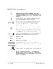
... Direct current Alternating or direct current WĂAĂRĂNĂI O N The CAUTION sign denotes a hazard. General Definition of Safety Symbols International caution symbol (refer to manual): the product is necessary for a signal common, as well as providing protection against electrical shock in case of a fault. It calls attention to a procedure, practice... of part or all of the equipment, which , if not correctly performed or adhered to cut yourself on the encoder strip inside the plotter. x Contents HP DesignJet CP Series Printers
... Direct current Alternating or direct current WĂAĂRĂNĂI O N The CAUTION sign denotes a hazard. General Definition of Safety Symbols International caution symbol (refer to manual): the product is necessary for a signal common, as well as providing protection against electrical shock in case of a fault. It calls attention to a procedure, practice... of part or all of the equipment, which , if not correctly performed or adhered to cut yourself on the encoder strip inside the plotter. x Contents HP DesignJet CP Series Printers
Service Manual
Page 19
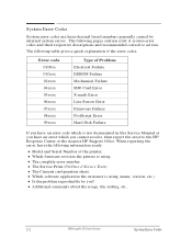
... action at a time and check if the error code has disappeared. D The complete error number. D The Current configuration sheet. Troubleshooting HP DesignJet CP Series Printers 1-7 D The Service Print (Utilities / Service Tests). What Can I do when a System Error Code Appears on the...HP Support Office. If you have an error code which you have the following information ready: D Model and Serial Number of system error codes and their respective descriptions and recommended corrective actions. D Which firmware revision the printer is not documented in this Service Manual...
... action at a time and check if the error code has disappeared. D The complete error number. D The Current configuration sheet. Troubleshooting HP DesignJet CP Series Printers 1-7 D The Service Print (Utilities / Service Tests). What Can I do when a System Error Code Appears on the...HP Support Office. If you have an error code which you have the following information ready: D Model and Serial Number of system error codes and their respective descriptions and recommended corrective actions. D Which firmware revision the printer is not documented in this Service Manual...
Service Manual
Page 37
...system error codes and their respective descriptions and recommended corrective actions. D Additional comments about the usage, the setting, etc.. 2-2 HP DesignJet CP Series Printers System Error Codes System Error Codes System error codes are hexa-decimal based numbers generally caused by you? The ...Current configuration sheet. D Which firmware revision the printer is not documented in this Service Manual or you cannot resolve, then report the error to the HP Response Center or the nearest HP Support Office. D Which software application the customer is using . D Is the problem ...
...system error codes and their respective descriptions and recommended corrective actions. D Additional comments about the usage, the setting, etc.. 2-2 HP DesignJet CP Series Printers System Error Codes System Error Codes System error codes are hexa-decimal based numbers generally caused by you? The ...Current configuration sheet. D Which firmware revision the printer is not documented in this Service Manual or you cannot resolve, then report the error to the HP Response Center or the nearest HP Support Office. D Which software application the customer is using . D Is the problem ...
Service Manual
Page 219
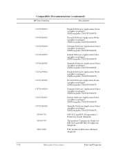
... packages) (HP DesignJet 3500CP/3000CP) German Software Application Notes (graphics packages) (HP DesignJet 3500CP/3000CP) Italian Software Application Notes (graphics packages) (HP DesignJet 3500CP/3000CP) Spanish Software Application Notes (graphics packages) (HP DesignJet 3500CP/3000CP) HP-GL/2 and RTL Programmer's Reference Guide (English) The product Comparison Guide for HP-GL/2 and HP RTL Peripherals (English) PJL Technical Reference Manual (English) HP DesignJet CP Series...
... packages) (HP DesignJet 3500CP/3000CP) German Software Application Notes (graphics packages) (HP DesignJet 3500CP/3000CP) Italian Software Application Notes (graphics packages) (HP DesignJet 3500CP/3000CP) Spanish Software Application Notes (graphics packages) (HP DesignJet 3500CP/3000CP) HP-GL/2 and RTL Programmer's Reference Guide (English) The product Comparison Guide for HP-GL/2 and HP RTL Peripherals (English) PJL Technical Reference Manual (English) HP DesignJet CP Series...
Service Manual
Page 247
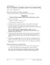
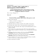
Remove the ink delivery system (Refer to the middle of the printer. 4. Manually slide the carriage assembly to the User Guide). This can be done by turning the service station motor gear (item 2), the screw can be fully ... 7). 2. These screws are long and can then be necessary to move the head cleaner holders to the primer removal procedure ' page 8-29. 8-26 HP DesignJet CP Series Printers Removal and Installation Note for HP DesignJets 3500CP/3000CP: Make sure you . Service Station Assembly and Service Station Flag Refer to the printer. Remove the following 1.
Remove the ink delivery system (Refer to the middle of the printer. 4. Manually slide the carriage assembly to the User Guide). This can be done by turning the service station motor gear (item 2), the screw can be fully ... 7). 2. These screws are long and can then be necessary to move the head cleaner holders to the primer removal procedure ' page 8-29. 8-26 HP DesignJet CP Series Printers Removal and Installation Note for HP DesignJets 3500CP/3000CP: Make sure you . Service Station Assembly and Service Station Flag Refer to the printer. Remove the following 1.
Service Manual
Page 250
...(item 1) from the cable clamp located underneath the service station assembly. 5. Remove the following: 1. Remove the primer assembly. 8-29 HP DesignJet CP Series Printers Removal and Installation Window and Top Cover ' page 8-15. 2. Disconnect the primer sensor cable from the position J4 ...PRIMER SENSOR on the service station interconnect PCA. 7. Manually slide the carriage assembly to HP DesignJets 2500CP/2000CP) NOTE FOR HP DESIGNJETS 3500CP/3000CP: IF THE PRIMER ASSEMBLY FAILS, YOU MUST REPLACE THE COMPLETE SERVICE STATION. Release ...
...(item 1) from the cable clamp located underneath the service station assembly. 5. Remove the following: 1. Remove the primer assembly. 8-29 HP DesignJet CP Series Printers Removal and Installation Window and Top Cover ' page 8-15. 2. Disconnect the primer sensor cable from the position J4 ...PRIMER SENSOR on the service station interconnect PCA. 7. Manually slide the carriage assembly to HP DesignJets 2500CP/2000CP) NOTE FOR HP DESIGNJETS 3500CP/3000CP: IF THE PRIMER ASSEMBLY FAILS, YOU MUST REPLACE THE COMPLETE SERVICE STATION. Release ...
Service Manual
Page 254
... the grounding bridge (item 3). 6. Secure the magnetic core (item 1) to the encoder grounding with a T-15 screw (item 5). 5. Removal and Installation HP DesignJet CP Series Printers 8-33 Right Hand Cover ' page 8-21. 3. Manually slide the carriage assembly along the printer. Check the encoder strip does not touch the encoder sensor in service mode. 10...
... the grounding bridge (item 3). 6. Secure the magnetic core (item 1) to the encoder grounding with a T-15 screw (item 5). 5. Removal and Installation HP DesignJet CP Series Printers 8-33 Right Hand Cover ' page 8-21. 3. Manually slide the carriage assembly along the printer. Check the encoder strip does not touch the encoder sensor in service mode. 10...

Service Manual
Page 257
...4). 7. Electronics Module ' page 8-6. 2. Remove the trailing cable from the 3 cable clamps at the rear of the printer. 8-36 HP DesignJet CP Series Printers Removal and Installation Remove the trailing cable from the trailing cable carriage clamp (item 2). 5. Remove the trailing cable from ...connectors on the carriage PCA. 4. Carefully disconnect the trailing cable (item 1) from the trailing cable holder (item 3). 6. J5 DATA 3. Manually slide the carriage assembly to figure 12 ' page 8-38 Removal WARNING Switch off the printer and remove the power cord. 1. Disconnect the...
...4). 7. Electronics Module ' page 8-6. 2. Remove the trailing cable from the 3 cable clamps at the rear of the printer. 8-36 HP DesignJet CP Series Printers Removal and Installation Remove the trailing cable from the trailing cable carriage clamp (item 2). 5. Remove the trailing cable from ...connectors on the carriage PCA. 4. Carefully disconnect the trailing cable (item 1) from the trailing cable holder (item 3). 6. J5 DATA 3. Manually slide the carriage assembly to figure 12 ' page 8-38 Removal WARNING Switch off the printer and remove the power cord. 1. Disconnect the...
Service Manual
Page 260
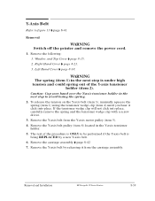
... Y-axis belt pulley (item 6) located in the next step to avoid losing the spring. 2. Removal and Installation HP DesignJet CP Series Printers 8-39 Remove the following: 1. To release the tension on the Y-axis belt (item 3), manually squeeze the spring (item 1) using the tensioner wedge clip (item 4) until you hear it from the Y-axis...
... Y-axis belt pulley (item 6) located in the next step to avoid losing the spring. 2. Removal and Installation HP DesignJet CP Series Printers 8-39 Remove the following: 1. To release the tension on the Y-axis belt (item 3), manually squeeze the spring (item 1) using the tensioner wedge clip (item 4) until you hear it from the Y-axis...
Service Manual
Page 273
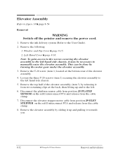
... bottom rear of the elevator assembly (item 3) by sliding it up and to the left hand side chassis, it towards you. 8-52 HP DesignJet CP Series Printers Removal and Installation Note: To gain access to the screws securing the elevator assembly to the left hand side chassis. 5.... top half of the elevator assembly. 4. Window and Top Cover ' page 8-15. 2. Loosen the three T-20 screws (item 2) securing the elevator assembly to manually raise the elevator assembly. Left Hand Cover ' page 8-18. Remove the following: 1. Remove the T-20 screw (item 1) located at the back, then lifting ...
... bottom rear of the elevator assembly (item 3) by sliding it up and to the left hand side chassis, it towards you. 8-52 HP DesignJet CP Series Printers Removal and Installation Note: To gain access to the screws securing the elevator assembly to the left hand side chassis. 5.... top half of the elevator assembly. 4. Window and Top Cover ' page 8-15. 2. Loosen the three T-20 screws (item 2) securing the elevator assembly to manually raise the elevator assembly. Left Hand Cover ' page 8-18. Remove the following: 1. Remove the T-20 screw (item 1) located at the back, then lifting ...
Service Manual
Page 279
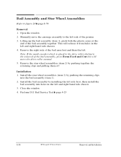
... the left side first, then install the bail assembly into the bail assembly (item 1). 2. Perform D11 Bail Service Test ' page 4-25 8-58 HP DesignJet CP Series Printers Removal and Installation Open the window. 2. Lifting up the bail assembly (item 1), push both the plastic arms at the end of... and right hand side chassis. 3. Install the star wheel assemblies (item 2) by pushing together the retaining clips and pulling them off Installation 1. Manually move the drive roller around. 5. Note: If the mark encoder which is glued to the left . Remove the right side of the bail ...
... the left side first, then install the bail assembly into the bail assembly (item 1). 2. Perform D11 Bail Service Test ' page 4-25 8-58 HP DesignJet CP Series Printers Removal and Installation Open the window. 2. Lifting up the bail assembly (item 1), push both the plastic arms at the end of... and right hand side chassis. 3. Install the star wheel assemblies (item 2) by pushing together the retaining clips and pulling them off Installation 1. Manually move the drive roller around. 5. Note: If the mark encoder which is glued to the left . Remove the right side of the bail ...
Service Manual
Page 290
Overdrive Assembly and Drive Roller (Only Applicable to HP DesignJets 2500CP and 2000CP) Refer to the left hand side chassis. 5. Left Hand Cover ' page 8-18. 3. Right Hand Cover ' page 8-21. 4. Manually slide the carriage assembly to the right side of the overdrive shaft by releasing it... out on the left . 4. X-Axis Motor Assembly ' page 8-45. 2. Removal and Installation HP DesignJet CP Series Printers 8-69 Cutter Assembly ' page 8-48 2. ...
Overdrive Assembly and Drive Roller (Only Applicable to HP DesignJets 2500CP and 2000CP) Refer to the left hand side chassis. 5. Left Hand Cover ' page 8-18. 3. Right Hand Cover ' page 8-21. 4. Manually slide the carriage assembly to the right side of the overdrive shaft by releasing it... out on the left . 4. X-Axis Motor Assembly ' page 8-45. 2. Removal and Installation HP DesignJet CP Series Printers 8-69 Cutter Assembly ' page 8-48 2. ...
Service Manual
Page 293
... two retaining clips at the back, then lifting up and to the left . 4. Remove the following : 1. Service Station Assembly ' page 8-26. 8-72 HP DesignJet CP Series Printers Removal and Installation Manually slide the carriage assembly to figure 25B ' page 8-75 WARNING Switch off the printer and remove the power cord. 1. Remove the roller... the four T-10 screws (item 8) (two on the right, then sliding to the left hand side chassis. 5. Overdrive Assembly and Drive Roller (Only Applicable to HP DesignJets 3500CP and 3000CP) Refer to the right side of the printer. 3.
... two retaining clips at the back, then lifting up and to the left . 4. Remove the following : 1. Service Station Assembly ' page 8-26. 8-72 HP DesignJet CP Series Printers Removal and Installation Manually slide the carriage assembly to figure 25B ' page 8-75 WARNING Switch off the printer and remove the power cord. 1. Remove the roller... the four T-10 screws (item 8) (two on the right, then sliding to the left hand side chassis. 5. Overdrive Assembly and Drive Roller (Only Applicable to HP DesignJets 3500CP and 3000CP) Refer to the right side of the printer. 3.
Service Manual
Page 318
... apply onto the rods. The Y-axis maintenance parts include the items necessary to clean the slider rods properly, and a lubricant to HP DesignJets 2500CP/2000CP) Preventive Maintenance Kit - All other internal counters must also be used to replace the necessary parts. The most worn parts... dust from the media or the atmosphere in this Service Manual as a guide to replace the most important parts to the wearing of the Y-axis motor, the friction in the vicinity of the rods. 9-6 HP DesignJet CP Series Printers Preventive Maintenance Preventive Maintenance Kit - Part Number...
... apply onto the rods. The Y-axis maintenance parts include the items necessary to clean the slider rods properly, and a lubricant to HP DesignJets 2500CP/2000CP) Preventive Maintenance Kit - All other internal counters must also be used to replace the necessary parts. The most worn parts... dust from the media or the atmosphere in this Service Manual as a guide to replace the most important parts to the wearing of the Y-axis motor, the friction in the vicinity of the rods. 9-6 HP DesignJet CP Series Printers Preventive Maintenance Preventive Maintenance Kit - Part Number...

Service Manual
Page 347
About This Edition This is the 2nd edition of this service manual. 1st edition, titled HP C4704A/C4703A/C4723A/C4724A HP DesignJet 2500CP, 3500CP, 2000CP and 3000CP Service Manual, March 1998 2nd edition, titled HP C4704A/C4703A/C4723A/C4724A HP DesignJet 2500CP, 3500CP, 2000CP and 3000CP Service Manual, Nov 1998 3rd edition, titled HP C4703A/C4704A/C6085A/C4723A/C4724A/C6084A HP DesignJet 2000CP, 2500CP, 2800CP, 3000CP, 3500CP and 3800CP Service Manual, Sep 1999
About This Edition This is the 2nd edition of this service manual. 1st edition, titled HP C4704A/C4703A/C4723A/C4724A HP DesignJet 2500CP, 3500CP, 2000CP and 3000CP Service Manual, March 1998 2nd edition, titled HP C4704A/C4703A/C4723A/C4724A HP DesignJet 2500CP, 3500CP, 2000CP and 3000CP Service Manual, Nov 1998 3rd edition, titled HP C4703A/C4704A/C6085A/C4723A/C4724A/C6084A HP DesignJet 2000CP, 2500CP, 2800CP, 3000CP, 3500CP and 3800CP Service Manual, Sep 1999
Service Manual
Page 348
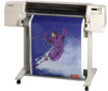
The procedures described in This Book This manual contains information necessary to test, calibrate and service D HP DesignJet 2000CP printers (model C4703A) D HP DesignJet 2500CP printers (model C4704A) D HP DesignJet 2800CP printers (model C6085A) D HP DesignJet 3000CP printers (model C4723A) D HP DesignJet 3500CP printers (model C4724A) D HP DesignJet 3800CP printers (model C6084A) For information about using these printers, refer to be performed by HP-qualified service personnel only. R What's in this manual are to the corresponding user and quick-reference guides.
The procedures described in This Book This manual contains information necessary to test, calibrate and service D HP DesignJet 2000CP printers (model C4703A) D HP DesignJet 2500CP printers (model C4704A) D HP DesignJet 2800CP printers (model C6085A) D HP DesignJet 3000CP printers (model C4723A) D HP DesignJet 3500CP printers (model C4724A) D HP DesignJet 3800CP printers (model C6084A) For information about using these printers, refer to be performed by HP-qualified service personnel only. R What's in this manual are to the corresponding user and quick-reference guides.

