
HP PCL/PJL reference - PCL 5 Comparison Guide
Page 62
... white and a "0" is Texture OR Source) Operands • Source objects: character cell, raster image, rule, HP-GL/2 vectors and polygons • Texture: pattern mask • Destination: current page definition Assuming three bits per pixel, the following diagram shows the print model process. Operators • Source Transparency (specified before logical operation; The print...
... white and a "0" is Texture OR Source) Operands • Source objects: character cell, raster image, rule, HP-GL/2 vectors and polygons • Texture: pattern mask • Destination: current page definition Assuming three bits per pixel, the following diagram shows the print model process. Operators • Source Transparency (specified before logical operation; The print...
Service Manual
Page 9
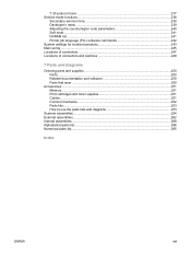
... 242 System settings for localized products 243 Main wiring ...245 Locations of connectors ...247 Locations of connectors and switches 248 7 Parts and diagrams Ordering parts and supplies 250 Parts...250 Related documentation and software 250 Parts that wear ...250 Accessories...251 Memory...2. 51 Print cartridges and... toner supplies 251 Cables...251 Common hardware ...252 Parts kits...253 How to use the parts lists and diagrams 253 Scanner assemblies...254 External assemblies...262 Internal assemblies...268 Alphabetical parts list...286 Numerical parts list...295 Index ENWW vii
... 242 System settings for localized products 243 Main wiring ...245 Locations of connectors ...247 Locations of connectors and switches 248 7 Parts and diagrams Ordering parts and supplies 250 Parts...250 Related documentation and software 250 Parts that wear ...250 Accessories...251 Memory...2. 51 Print cartridges and... toner supplies 251 Cables...251 Common hardware ...252 Parts kits...253 How to use the parts lists and diagrams 253 Scanner assemblies...254 External assemblies...262 Internal assemblies...268 Alphabetical parts list...286 Numerical parts list...295 Index ENWW vii

Service Manual
Page 14
...-panel bezel (4 of 4 66 Product configuration 68 Printer timing diagram 70 Optical diagram of scanner 76 Document scanner path 78 Printer unit functional block diagram 79 ECU loads ...81 High-voltage power supply circuit 83 Overview of laser/scanner operation 84 Image-formation block diagram 85 Printer paper path 87 Solenoid, photosensors, and switches 88...
...-panel bezel (4 of 4 66 Product configuration 68 Printer timing diagram 70 Optical diagram of scanner 76 Document scanner path 78 Printer unit functional block diagram 79 ECU loads ...81 High-voltage power supply circuit 83 Overview of laser/scanner operation 84 Image-formation block diagram 85 Printer paper path 87 Solenoid, photosensors, and switches 88...

Service Manual
Page 46
Press MENU/ENTER. 2. To see which settings are currently selected, print a configuration report. Use the < or > button to select one of the options from the submenu, and then press MENU/ ENTER. 4. Table 2-1. Control-panel menu structure Main Menu Submenu Submenu Fax Job status Fax...Date, Header Time/Date Fax Header Copy setup Default Quality Def. Collation Def. # of copies Def. Control-panel menu structure Use the following hierarchical diagram of the control-panel menu structure to make changes to begin. 2. Light/Dark Def. Press MENU/ENTER to settings and features.
Press MENU/ENTER. 2. To see which settings are currently selected, print a configuration report. Use the < or > button to select one of the options from the submenu, and then press MENU/ ENTER. 4. Table 2-1. Control-panel menu structure Main Menu Submenu Submenu Fax Job status Fax...Date, Header Time/Date Fax Header Copy setup Default Quality Def. Collation Def. # of copies Def. Control-panel menu structure Use the following hierarchical diagram of the control-panel menu structure to make changes to begin. 2. Light/Dark Def. Press MENU/ENTER to settings and features.

Service Manual
Page 86
Printer timing diagram 70 Chapter 4 Operational overview ENWW The timing diagram in the basic sequence of operation for the printer. Printer timing diagram illustrates which components are affected during each of the periods in Figure 4-2. Figure 4-2.
Printer timing diagram 70 Chapter 4 Operational overview ENWW The timing diagram in the basic sequence of operation for the printer. Printer timing diagram illustrates which components are affected during each of the periods in Figure 4-2. Figure 4-2.

Service Manual
Page 92
... bits per inch (ppi). The mirrors direct the light through the LIU as a copy, sending it through the lens to the next raster line. Optical diagram of scanner The scanner lamp illuminates a small strip of these elements: ● a lamp (cold-cathode fluorescent bulb) ● five mirrors and a lens ● a CCD Scanner...
... bits per inch (ppi). The mirrors direct the light through the LIU as a copy, sending it through the lens to the next raster line. Optical diagram of scanner The scanner lamp illuminates a small strip of these elements: ● a lamp (cold-cathode fluorescent bulb) ● five mirrors and a lens ● a CCD Scanner...

Service Manual
Page 94
...the presence of the scanner assembly. The message Doc feeder jam. appears on the control-panel display. ● Stall jam-When a page that detect paper. One other sensor detects an open flag Separation pad Cleanout Form sensor Paper present sensor Pre-pick roller Picks top sheet INPUT TRAY PAGE EJECTS FULLY... paper feeding and a jam message appears on the right side of media in the ADF and the scan module remains under any of the following diagram shows the ADF paper path. appears on the control-panel display. ● Other-If the paper stops in the ADF input tray. ADF paper ...
...the presence of the scanner assembly. The message Doc feeder jam. appears on the control-panel display. ● Stall jam-When a page that detect paper. One other sensor detects an open flag Separation pad Cleanout Form sensor Paper present sensor Pre-pick roller Picks top sheet INPUT TRAY PAGE EJECTS FULLY... paper feeding and a jam message appears on the right side of media in the ADF and the scan module remains under any of the following diagram shows the ADF paper path. appears on the control-panel display. ● Other-If the paper stops in the ADF input tray. ADF paper ...

Service Manual
Page 95
... SYSTEM Engine control unit (power system) The engine control unit (ECU) coordinates all print engine activities, drives the laser, and coordinates print data from the formatter with the image-formation process. In several other HP LaserJet products, the ECU is a block diagram of the printer and its relationship to the ADF/scanner and LIU.
... SYSTEM Engine control unit (power system) The engine control unit (ECU) coordinates all print engine activities, drives the laser, and coordinates print data from the formatter with the image-formation process. In several other HP LaserJet products, the ECU is a block diagram of the printer and its relationship to the ADF/scanner and LIU.

Service Manual
Page 101
...charge on the drum surface to the media. Transfer stage-During this process, a modulated laser diode projects the beam onto a rotating scanning mirror. Image-formation block diagram The seven image-formation processes 1. Image formation consists of each sweep, the beam strikes ...the beam-detect lens, generating the beam-detect signal (BD signal). Image-formation system Laser printing requires the interaction of several ...
...charge on the drum surface to the media. Transfer stage-During this process, a modulated laser diode projects the beam onto a rotating scanning mirror. Image-formation block diagram The seven image-formation processes 1. Image formation consists of each sweep, the beam strikes ...the beam-detect lens, generating the beam-detect signal (BD signal). Image-formation system Laser printing requires the interaction of several ...

Service Manual
Page 114
... and ground the print engine chassis before removing other parts. 1. To prevent damage, do not expose the print cartridge to remove on one of the diagrams. 2. Locate the part that you open the print-cartridge door. 1. After performing service ● Replace the print cartridge. ●...bright light. Cover it from the wall receptacle. ● Place the product on the first diagram, separation of paper. Remove the print cartridge Parts removal order Use the following diagrams to determine which parts must be removed before servicing the product. ● Remove the print ...
... and ground the print engine chassis before removing other parts. 1. To prevent damage, do not expose the print cartridge to remove on one of the diagrams. 2. Locate the part that you open the print-cartridge door. 1. After performing service ● Replace the print cartridge. ●...bright light. Cover it from the wall receptacle. ● Place the product on the first diagram, separation of paper. Remove the print cartridge Parts removal order Use the following diagrams to determine which parts must be removed before servicing the product. ● Remove the print ...

Service Manual
Page 115
... (also requires removing formatter) paper lift-plate assembly Parts removal order (1 of 2) ENWW Removal and replacement strategy 99 If the part is on the second diagram, you are required to separate the scanner from the printer before removing the part. Figure 5-2. 3.
... (also requires removing formatter) paper lift-plate assembly Parts removal order (1 of 2) ENWW Removal and replacement strategy 99 If the part is on the second diagram, you are required to separate the scanner from the printer before removing the part. Figure 5-2. 3.

Service Manual
Page 254
... display reads Ready. 2. You can gain access to adjust certain global settings such as the country/region. Service-mode functions Use the following is a hierarchical diagram of the secondary service menu.
... display reads Ready. 2. You can gain access to adjust certain global settings such as the country/region. Service-mode functions Use the following is a hierarchical diagram of the secondary service menu.

Service Manual
Page 255
... developer's menu to adjust fax data-store parameters and to select Service reports, and press MENU/ENTER. 2. Service-mode functions 239 The following is a hierarchical diagram of all the Fax data-store parameters 1. Simultaneously press the * and # buttons on the keypad. You can gain access to the developer's menu from the...
... developer's menu to adjust fax data-store parameters and to select Service reports, and press MENU/ENTER. 2. Service-mode functions 239 The following is a hierarchical diagram of all the Fax data-store parameters 1. Simultaneously press the * and # buttons on the keypad. You can gain access to the developer's menu from the...
Service Manual
Page 265
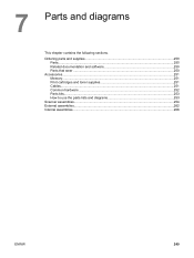
Ordering parts and supplies 250 Parts...250 Related documentation and software 250 Parts that wear ...250 Accessories...251 Memory...2. 51 Print cartridges and toner supplies 251 Cables...251 Common hardware ...252 Parts kits...253 How to use the parts lists and diagrams 253 Scanner assemblies...254 External assemblies...262 Internal assemblies...268 ENWW 249 7 Parts and diagrams This chapter contains the following sections.
Ordering parts and supplies 250 Parts...250 Related documentation and software 250 Parts that wear ...250 Accessories...251 Memory...2. 51 Print cartridges and toner supplies 251 Cables...251 Common hardware ...252 Parts kits...253 How to use the parts lists and diagrams 253 Scanner assemblies...254 External assemblies...262 Internal assemblies...268 ENWW 249 7 Parts and diagrams This chapter contains the following sections.

Service Manual
Page 266
..." field at the following website: https//partsdirect.hp.com/epdo/default/ mainmenu.asp. Table 7-1. HP Online Technical Support Software drivers, support documentation, and answers to frequently asked questions http://www.hp.com/support HP Technical Training (North America) Classes and schedules ...Life expectancies of the page. Technical support websites HP Connect Online (for HP partners) http://www.connect-online.hp.com HP Customer Care Call Centers http://www.hp.com/support/callcenters Information for contacting HP call centers in Table 3-1. Related documentation and software...
..." field at the following website: https//partsdirect.hp.com/epdo/default/ mainmenu.asp. Table 7-1. HP Online Technical Support Software drivers, support documentation, and answers to frequently asked questions http://www.hp.com/support HP Technical Training (North America) Classes and schedules ...Life expectancies of the page. Technical support websites HP Connect Online (for HP partners) http://www.connect-online.hp.com HP Customer Care Call Centers http://www.hp.com/support/callcenters Information for contacting HP call centers in Table 3-1. Related documentation and software...
Service Manual
Page 268
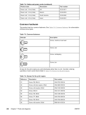
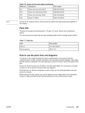
... XA9-0828-000CN XA9-1420-000CN XA9-1421-000CN XA9-1495-000CN XA9-1503-000CN XA9-1504-000CN RB9-0818-000CN 252 Chapter 7 Parts and diagrams ENWW Screws for the print engine are sold individually rather than in Table 7-6. Common fasteners for the print engine. Screws for a description of each screw...
... XA9-0828-000CN XA9-1420-000CN XA9-1421-000CN XA9-1495-000CN XA9-1503-000CN XA9-1504-000CN RB9-0818-000CN 252 Chapter 7 Parts and diagrams ENWW Screws for the print engine are sold individually rather than in Table 7-6. Common fasteners for the print engine. Screws for a description of each screw...
Service Manual
Page 269
... for the screws are not listed in this chapter. For convenience, the part numbers for the print engine are included within the diagrams. Parts that the part number selected is for the item, and a description of the product are not field-replaceable units and cannot be ordered.... for a part number, pay careful attention to make sure that have no reference designator or part number are listed in the appropriate parts diagrams in this chapter illustrate the major subassemblies in the description column to the voltage listed in the product and their component parts. Screws for the...
... for the screws are not listed in this chapter. For convenience, the part numbers for the print engine are included within the diagrams. Parts that the part number selected is for the item, and a description of the product are not field-replaceable units and cannot be ordered.... for a part number, pay careful attention to make sure that have no reference designator or part number are listed in the appropriate parts diagrams in this chapter illustrate the major subassemblies in the description column to the voltage listed in the product and their component parts. Screws for the...

Service Manual
Page 272
Scanner covers and ADF 256 Chapter 7 Parts and diagrams ENWW Figure 7-2.
Scanner covers and ADF 256 Chapter 7 Parts and diagrams ENWW Figure 7-2.

Service Manual
Page 274
ADF rollers and separation pad 258 Chapter 7 Parts and diagrams ENWW Figure 7-3.
ADF rollers and separation pad 258 Chapter 7 Parts and diagrams ENWW Figure 7-3.

Service Manual
Page 280
1 2 S1 S7 9 S7 3 4 8 S9 7 S6 S9 Figure 7-6. Printer covers 5 10 6 264 Chapter 7 Parts and diagrams ENWW
1 2 S1 S7 9 S7 3 4 8 S9 7 S6 S9 Figure 7-6. Printer covers 5 10 6 264 Chapter 7 Parts and diagrams ENWW


